Fredrick Ramond Jolie FR30103BX Handleiding
Fredrick Ramond
Lamp
Jolie FR30103BX
Bekijk gratis de handleiding van Fredrick Ramond Jolie FR30103BX (3 pagina’s), behorend tot de categorie Lamp. Deze gids werd als nuttig beoordeeld door 10 mensen en kreeg gemiddeld 4.6 sterren uit 5.5 reviews. Heb je een vraag over Fredrick Ramond Jolie FR30103BX of wil je andere gebruikers van dit product iets vragen? Stel een vraag
Pagina 1/3

Item No. FR30103
Numéro d’article: FR30103 Número del artículo: FR30103
english spanish
french
J IE JOLIE IEOL JOL
{ DRAWING 1 }
3
4
2
1
5
{ DRAWING 2 }
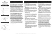
SAFETY WARNING: READ WIRING AND GROUNDING INSTRUC-
TIONS (I.S. 18) AND ANY ADDITIONAL DIRECTIONS. TURN
POWER SUPPLY OFF DURING INSTALLATION. IF NEW WIRING IS
REQUIRED, CONSULT A QUALIFIED ELECTRICIAN OR LOCAL
AUTHORITIES FOR CODE REQUIREMENTS.
Make electrical connections from supply wire to fixture lead wires.
Refer to instruction sheet and follow all instructions to make (I.S. 18)
all necessary wiring connections. Then refer back to this sheet to
complete installation of this fixture.
Shut off electrical current befoer starting. If the fixture you are replacing is
turned on and off by a wall switch, simply turn the switch off. If not,
remove the appropriate fuse (or open the circuit breakers) until the fixture
until the new fixture is completely wired and in place.
WIRES
STEM
ue
r
e
minaire
É
ADVERTENCIA DE SEGURIDAD: LEA LAS INSTRUCCIONES
DE CABLEADO Y CONEXIÓN A TIERRA (I.S. 18) Y LAS
INSTRUCCIONES ADICIONALES. APAGUE LA ALIMENTACIÓN
ELÉCTRICA DURANTE LA INSTALACIÓN. SI SE REQUIERE UN
NUEVO CABLEADO, CONSULTE A UN ELECTRICISTA CUALI-
FICADO OA LAS AUTORIDADES LOCALES PARA OBTENER
LOS REQUISITOS DEL CÓDIGO.
AVERTISSEMENT DE SÉCURITÉ: LISEZ LES INSTRUCTIONS DE
CÂBLAGE ET DE MISE À LA TERRE (I.S. 18) ET TOUTES AUTRES
DIRECTIONS. ÉTEIGNEZ L'ALIMENTATION ÉLECTRIQUE
PENDANT L'INSTALLATION. SI UN NOUVEAU CÂBLAGE EST
NÉCESSAIRE, CONSULTEZ UN ÉLECTRICIEN QUALIFIÉ OU LES
AUTORITÉS LOCALES POUR OBTENIR DES CODIFICATIONS.
n
uc
odas las
f
ffectuer toutes les connexions de
r. Si el artefacto que
pared, simplemente apague el interruptor
fusible adecuado (o abra los interruptores automáticos) hasta que el
r
fusible, interruptor o interruptor
completamente conectado y en su lugar.
C
F
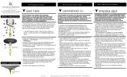
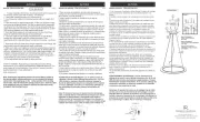
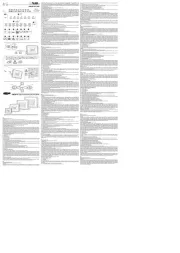
1. To assemble your fixture first take the canopy (C) with stem and slip
the wires exiting from the top of the fixture body (F) through the center of
the stem.
2. Now thread canopy and stem onto the top of the fixture body (F).
3. Fixture is ready for installation.
1. To mount the fixture to the ceiling, first thread the two long 8-32 screws
(1) provided, into the mounting strap (2). Making sure the screws are
threaded into the holes that match the mounting hole spacing (M) on
canopy (3). - see Drawing 2.
2. Attach the mounting strap to the junction box using two 8-32 screws.
NOT PROVIDED.
3. NOTE: Due to the weight of this fixture it has been supplied with a
safety cable. This cable must be attached to a joist or a structure indepen-
dent of the junction box. Follow instruction sheet (IS-SCC) provided.
4. Next make all necessary wiring connections following instruction sheet
(IS-18) provided.
5. Now lift fixture up to ceiling and slip the screws (1) through the holes
(M) in the canopy. Push wires into junction box and hold canopy up
against the ceiling and thread the barrel knobs (4) onto and of screws (1)
and tighten to secure the fixture to the ceiling.
1. Para ensamblar su accesorio, primero tome el dosel (C) con el
vástago y deslice los cables que salen de la parte superior del
cuerpo del accesorio (F) a través del centro del vástago.
2. Ahora enrosque el dosel y el vástago en la parte superior del
cuerpo del accesorio (F).
3. El accesorio está listo para su instalación.
1. Pour assembler votre luminaire, prenez d'abord l'auvent (C) avec la
tige et faites glisser les fils sortant du haut du corps du luminaire (F)
par le centre de la tige.
2. Maintenant, vissez la canopée et la tige sur le dessus du corps de
l'appareil (F).
3. L'appareil est prêt pour l'installation.
PASO 2
1. Para montar el aparato en el techo, primero enrosque los dos
tornillos largos 8-32 (1) incluidos en la correa de montaje (2).
Asegúrese de que los tornillos estén enroscados en los orificios
que coincidan con el espacio de los orificios de montaje (M) en
la cubierta (3). - vea el dibujo 2.
2. Fije la correa de montaje a la caja de conexiones con dos
tornillos 8-32. NO PROVISTO.
3. NOTA: Debido al peso de este aparato se p1-ha suministrado
con un cable de seguridad. Este cable debe estar conectado a
una viga o una estructura independiente de la caja de conex-
iones. Siga la hoja de instrucciones (IS-SCC) proporcionada.
4. A continuación, realice todas las conexiones de cableado
necesarias siguiendo la hoja de instrucciones (IS-18) proporcio-
nada.
5. Ahora levante el dispositivo hasta el techo y deslice los
tornillos (1) a través de los orificios (M) en la cubierta. Empuje
los cables en la caja de conexiones y sostenga la cubierta contra
el techo y enrosque las perillas cilíndricas (4) en los tornillos (1)
y apriételos para asegurar el accesorio al techo.
ÉTAPE 2
1. Pour monter l'appareil au plafond, vissez d'abord les deux longues
vis 8-32 (1) fournies dans la sangle de montage (2). Assurez-vous que
les vis sont vissées dans les trous qui correspondent à l'espacement
des trous de montage (M) sur l'auvent (3). - voir dessin 2.
2. Fixez la sangle de montage à la boîte de jonction à l'aide de deux
vis 8-32. NON FOURNI.
3. REMARQUE: en raison du poids de cet appareil, il a été fourni avec
un câble de sécurité. Ce câble doit être attaché à une solive ou à une
structure indépendante de la boîte de jonction. Suivez la feuille
d'instructions (IS-SCC) fournie.
4. Ensuite, effectuez toutes les connexions de câblage nécessaires en
suivant la feuille d'instructions (IS-18) fournie.
5. Soulevez maintenant le luminaire jusqu'au plafond et faites glisser
les vis (1) à travers les trous (M) de la verrière. Poussez les fils dans la
boîte de jonction et maintenez l'auvent contre le plafond et vissez les
boutons cylindriques (4) sur et des vis (1) et serrez pour fixer le
luminaire au plafond.
{ DRAWING 2 }
R
P
G
T
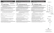
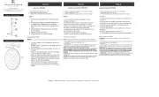
GLASS INSTALLATION:
NOTE: It is recommended that the glass be installed after fixture is hung.
1. To install glass first remove the barrel knob with threaded stud (T) and plastic
washer (P), from the top rail (R) of the fixture body (F) - see Drawing 3.
2. Next take a glass panel (G) and align the threaded hole in the top rail with the
hole in the top of the glass panel.
3. Now thread barrel knob with stud into threaded hole in top rail, making sure
plastic washer is between glass panel and base of barrel knob.
4. Continue adding panels around the fixture until all panels are installed.
INSTALACIÓN DE VIDRIO:
NOTA: Se recomienda instalar el vidrio después de colgar el accesorio.
1. Para instalar vidrio, primero retire la perilla del cilindro con el perno roscado
(T) y la arandela de plástico (P), del riel superior (R) del cuerpo del accesorio (F)
- vea el Dibujo 3 .
2. A continuación, tome un panel de vidrio (G) y alinee el orificio roscado del riel
superior con el orificio de la parte superior del panel de vidrio.
3. Ahora enrosque la perilla del cilindro con el perno en el orificio roscado del riel
superior, asegurándose de que la arandela de plástico esté entre el panel de
vidrio y la base de la perilla del cilindro.
4. Continúe agregando paneles alrededor del accesorio hasta que todos los
paneles estén instalados.
INSTALLATION DU VERRE:
REMARQUE: Il est recommandé d'installer la vitre une fois le luminaire
suspendu.
1. Pour installer le verre, retirez d'abord le bouton cylindrique avec le
goujon fileté (T) et la rondelle en plastique (P), du rail supérieur (R) du
corps de l'appareil (F) - voir Dessin 3.
2. Ensuite, prenez un panneau en verre (G) et alignez le trou fileté du rail
supérieur avec le trou situé en haut du panneau en verre.
3. Maintenant, vissez le bouton du barillet avec le goujon dans le trou
fileté du rail supérieur, en vous assurant que la rondelle en plastique se
trouve entre le panneau de verre et la base du bouton du barillet.
4. Continuez à ajouter des panneaux autour du luminaire jusqu'à ce que
tous les panneaux soient installés.

Wiring
Instructions for 0-10 volt LED dimmer
start here
Instrucciones de cableado para atenuador LED de 0-10 voltios
commencez ici
Instructions de câblage pour gradateur LED 0-10 volts
empezar aquí
J
WIRES FROM
DIMMER
SUPPLY WIRES
FROM
JUNCTION BOX
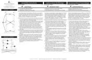
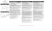
Your fixture is designed so it can use a standard incandescent
dimmer, Or a 0-10 volt LED dimmer. If a 0-10 volt LED dimmer is
used, it may be necessary to have additonal wiring installed from the
dimmer switch to the fixture. Consulting an electrician will be
necessary.
Su luminaria está diseñada para que pueda usar un atenuador
incandescente estándar o un atenuador LED de 0-10 voltios. Si se utiliza
un atenuador LED de 0-10 voltios, puede ser necesario instalar cableado
adicional desde el interruptor atenuador hasta la luminaria. Consultar a un
electricista será
Votre luminaire est conçu pour pouvoir utiliser un variateur à incandes-
cence standard ou un variateur LED 0-10 volts. Si un gradateur LED
0-10 volts est utilisé, il peut être nécessaire d'avoir un câblage supplé-
mentaire installé entre le variateur et le luminaire. Consulter un
électricien sera
DIMMER
DRAWING 1
SWITCH
D
B
W
G
P
1. If using the optional 0-10 volt dimmer there will be four wires exiting
the junction box. (B) Black [+], (W) White [-], wirng are for the 120 /
277 voltage. The (G) Gray {-} and (P) Purple {+} are for the 0-10 volt
wires from the dimmer (D) - see Drawing 1.
2. The fixture has four wires of corrisponding colors. When make the
wire connections follow the chart below.
Black (B) from junction box (J) wired to Black (B) from fixture (F).
White (W) from junction box (J) wired to White (W) from fixture (F).
Gray (G) from junction box (J) wired to Gray (G) from fixture (F).
Purple (P) from junction box (J) wired to Purple (P) from fixture (F).
3. After all wiring connections are made consult instruction sheet
(IS-19-50) to complete installation.
G
B
W
P
F
INCANDESCENT DIMMER USAGE:
If using an incadescent dimmer follow manufactures instructions.
NOTE: MAKE SURE TO CAP OFF THE GRAY AND PURPLE WIRE
FROM THE FIXTURE INSIDE THE CANOPY. IF THE ARE NOT
CAPPED THEY CAN SHORT OUT AND CAUSE THE FIXTURE TO
FAIL.
1. Si usa el atenuador opcional de 0-10 voltios, habrá cuatro cables
saliendo de la caja de conexiones. (B) Negro [+], (W) Blanco [-], los
cables son para el voltaje 120/277. El (G) Gris {-} y (P) Morado {+} son
para los cables de 0-10 voltios del atenuador (D); consulte el Dibujo 1.
2. La luminaria tiene cuatro hilos de colores correspondientes. Al realizar
las conexiones de cables, siga la tabla a continuación.
Negro (B) de la caja de conexiones (J) cableado a Negro (B) de la
luminaria (F).
Blanco (W) de la caja de conexiones (J) cableado al blanco (W) de la
luminaria (F).
Gris (G) de la caja de conexiones (J) cableada a Gris (G) de la luminaria
(F).
Púrpura (P) de la caja de conexiones (J) cableada a Púrpura (P) de la
luminaria (F).
3. Una vez realizadas todas las conexiones de cableado, consulte la hoja
de instrucciones (IS-19-50) para completar la instalación.
1. Si vous utilisez le gradateur optionnel 0-10 volts, quatre fils sortent de
la boîte de jonction. (B) Noir [+], (W) Blanc [-], le câblage est pour la
tension 120/277. Les (G) Gray {-} et (P) Purple {+} sont pour les fils 0-10
volts du gradateur (D) - voir Schéma 1.
2. Le luminaire a quatre fils de couleurs correspondantes. Lorsque vous
effectuez les connexions des fils, suivez le tableau ci-dessous.
Noir (B) de la boîte de jonction (J) câblé au noir (B) du luminaire (F).
Blanc (W) de la boîte de jonction (J) câblé au blanc (W) du luminaire (F).
Gris (G) de la boîte de jonction (J) câblé au gris (G) du luminaire (F).
Violet (P) de la boîte de jonction (J) câblé au violet (P) du luminaire (F).
3. Après avoir effectué toutes les connexions de câblage, consultez la
feuille d'instructions (IS-19-50) pour terminer l'installation.
USO INCANDESCENTE DEL DIMMER:
Si usa un atenuador incadescente, siga las instrucciones del fabricante.
NOTA: ASEGÚRESE DE TAPAR EL CABLE GRIS Y PÚRPURA DE LA
LUMINARIA DENTRO DEL DOSEL. SI NO ESTÁN TAPADOS, CAUSAN
UN CORTOCIRCUITO Y LA LUMINARIA NO FUNCIONA.
UTILISATION INCANDESCENTE DU DIMMER:
Si vous utilisez un variateur à incandescence, suivez les instructions du
fabricant.
REMARQUE: ASSUREZ-VOUS DE COUVERCLE LE FIL GRIS ET
VIOLET DU LUMINAIRE À L'INTÉRIEUR DE L'AUVENT. S'ILS NE
SONT PAS PLAFONNÉS, ILS PROVOQUENT UN COURT-CIRCUIT ET
LE LUMINAIRE NE FONCTIONNE PAS.

start here
commencez ici
empezar aquí
Item No.
Numéro d’article:
Número del artículo:
L I G H T I N G
HINKLEY
English Spanish
French
H I N K L E Y L I G H T I N G 330 00 Pin Oa k Parkway, Avon Lake, OH 44012 800 .44 6.5 539 / 440.653.5500 hinkle yli ght ing .co m
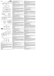
IS-SCC [safety cable installation]
Drawing 1 -
Safety Cable Installatio
n
junction
box
3
1
2
ceiling
joist
ADVERTENCIA: PARA EVITAR CHOQUE ELÉCTRICO,
ESTA SECCIÓN DE LA HOJA DE INSTRUCCIONES
ES EL ÚNICO PROPÓSITO DE INSTALACIÓN DEL
CABLE DE SEGURIDAD, Y NO DEBE SER UTILIZADO
PARA REALIZAR LAS CONEXIONES ELÉCTRICAS.
AVERTISSEMENT: POUR ÉVITER UNE ÉLECTROCUTION,
CETTE SECTION DE LA FEUILLE D'INSTRUCTIONS EST
DANS LE SEUL BUT DE CÂBLE DE SÉCURITÉ
INSTALLATION, ET NE DOIT PAS ÊTRE UTILISÉ POUR
FAIRE LES CONNEXIONS ÉLECTRIQUES.
WARNING: TO AVOID ELECTRICAL SHOCK, THIS SECTION
OF THE INSTRUCTION SHEET IS FOR THE SOLE PURPOSE
OF SAFETY CABLE INSTALLATION, AND IS NOT TO BE USED
TO MAKE ANY ELECTRICAL CONNECTIONS.
El cable de seguridad debe estar conectada a una vigueta
de techo u otra estructura permanente independiente de la
caja de conexiones.
1. Utilizando un 3/16 "de diámetro. Taladro, perfore un
agujero piloto (1). Debe ser perforado en la estructura
permanente oa través de la caja de conexiones en el lado
de la vigueta se el cable de seguridad será adjunto
- ver dibujo 1.
2. Inserte y enrosque un tornillo de retraso de 1/4 "de
cabeza hexagonal (2) (no incluido) en el orificio piloto.
3. Continuar la instalación de este aparato de acuerdo con
IS19-50 proporcionado.
4. Después se determina la longitud de cable de seguridad,
deje suficiente cable adicional para que pueda ser
envuelta alrededor de tornillo de tracción. Tema tirafondo
para fijar el cable de seguridad.
.
Le câble de sécurité doit être attaché à une solive du
plafond ou une autre structure permanente indépendante de
la boîte de jonction.
1. L'aide d'un foret de 3/16 "de diamètre., Percer un trou
pilote (1). Elle doit être foré dans la structure permanente ou
la boîte de jonction sur le côté solives ont le câble de sécurité
sera ci-joint - voir schéma 1.
2. Insérez et vissez une vis 1/4 "à tête hexagonale de retard
(2) (non inclus) dans le trou pilote.
3. Continuer l'installation de ce luminaire selon IS19-50 fourni.
4. Après longueur de câble de sécurité est déterminé,
prévoyez suffisamment de câble supplémentaire de sorte
qu'il peut être enroulé autour de la vis tire-fond. Sujet
décalage vis pour fixer le câble de sécurité.
The safety cable must be attached to a ceiling joist or other
permanent structure independent of the junction box.
1. using a 3/16" dia. drill, drill a pilot hole (1). It must be drilled into the
permanent structure or through the junction box on the joist side
were the safety cable will be attached - see Drawing 1.
2. Insert and thread a 1/4" hex head lag screw (2) (not included) into
pilot hole.
3. Continue installation of this xture according to IS19-50 provided.
4. After length of safety cable is determined, allow enough extra cable
so it can be wrapped around lag screw. Thread lag screw to secure
safety cable.
.
.
Make electrical connections from supply wire to fixture lead wires.
Refer to instruction sheet and follow all instructions to make (I.S. 18)
all necessary wiring connections. Then refer back to this sheet to
continue installatio of this fixture.
Haga las conexiones eléctricas del cable de alimentación los
cables conductores del luminario. Consulte la hoja de instrucciones
(IS 18) y siga todas las instrucciones para hacer todas las
conexiones necesarias. Entonces referirse a esta hoja para
continuar instalacion de este luminario.
Effectuer les connexions électriques du câble d'alimentation au
montage des fils conducteurs. Reportez-vous à la feuille d'instruction
(IS 18) et suivez les instructions pour faire toutes les connexions
nécessaires. Ensuite, se reporter à la fiche de continuer installatio
de ce luminaire.
IS-SCC [Instalación de cable de seguridad]
IS-SCC [installation de câbles de sécurité]
Product specificaties
| Merk: | Fredrick Ramond |
| Categorie: | Lamp |
| Model: | Jolie FR30103BX |
Heb je hulp nodig?
Als je hulp nodig hebt met Fredrick Ramond Jolie FR30103BX stel dan hieronder een vraag en andere gebruikers zullen je antwoorden
Handleiding Lamp Fredrick Ramond
16 April 2025

16 April 2025
16 April 2025

16 April 2025
16 April 2025
16 April 2025
16 April 2025
16 April 2025
16 April 2025
16 April 2025
Handleiding Lamp
- Qazqa
- Megatron
- Esotec
- Cotech
- Unilux
- Altman
- Honeycomb
- Gewiss
- Monacor
- Martin
- Omnilux
- Markslöjd
- Bolt
- Amaran
- Ecolight
Nieuwste handleidingen voor Lamp
13 September 2025

13 September 2025
12 September 2025
12 September 2025
12 September 2025
8 September 2025
8 September 2025
8 September 2025

6 September 2025
5 September 2025