Fredrick Ramond Cy FR41486BK Handleiding
Fredrick Ramond
Lamp
Cy FR41486BK
Bekijk gratis de handleiding van Fredrick Ramond Cy FR41486BK (3 pagina’s), behorend tot de categorie Lamp. Deze gids werd als nuttig beoordeeld door 9 mensen en kreeg gemiddeld 4.4 sterren uit 5 reviews. Heb je een vraag over Fredrick Ramond Cy FR41486BK of wil je andere gebruikers van dit product iets vragen? Stel een vraag
Pagina 1/3

start here
commencez ici empezar aquí
Mounting Instructions
Les Instructions D’assemblage
Instrucciones De Montaje
English Spanish
French
wire
wire
wire
SAFETY WARNING: READ WIRING AND GROUNDING INSTRUCTIONS
Wiring Instructions for 0-10 volt LED dimmer ) AND ANY ADDITIONAL
DIRECTIONS. TURN POWER SUPPLY OFF DURING INSTALLATION. IF NEW
WIRING IS REQUIRED, CONSULT A QUALIFIED ELECTRICIAN OR LOCAL
AUTHORITIES FOR CODE REQUIREMENTS.
Item no: FR41486
Número de artículo FR41486
Make electrical connections from supply wire to fixture lead wires. Refer to
instruction sheet and (I.S. )Wiring Instructions for 0-10 volt LED dimmer
follow all instructions to make all necessary wiring connections. Then refer
back to this sheet to complete installation of this fixture.
ADVERTENCIA DE SEGURIDAD: LEA LAS INSTRUCCIONES DE
CABLEADO Y PUESTA A TIERRA (Instrucciones de cableado para
atenuadores LED de 0 a 10 voltios) Y CUALQUIER INSTRUCCIÓN
ADICIONAL. APAGUE LA FUENTE DE ENERGÍA DURANTE LA
INSTALACIÓN. SI SE REQUIERE CABLEADO NUEVO, CONSULTE A
UN ELECTRICISTA CALIFICADO O A LAS AUTORIDADES LOCALES
PARA CONOCER LOS REQUISITOS DEL CÓDIGO.
AVERTISSEMENT DE SÉCURITÉ : LIRE LES INSTRUCTIONS DE
CÂBLAGE ET DE MISE À LA TERRE (Instructions de câblage pour le
variateur LED 0-10 volts) ET TOUTES INSTRUCTIONS
SUPPLÉMENTAIRES. COUPEZ L'ALIMENTATION ÉLECTRIQUE
PENDANT L'INSTALLATION. SI UN NOUVEAU CÂBLAGE EST
NÉCESSAIRE, CONSULTEZ UN ÉLECTRICIEN QUALIFIÉ OU LES
AUTORITÉS LOCALES POUR CONNAÎTRE LES EXIGENCES DU CODE.
Numéro d'article FR41486
HINKLEY ey.com 33000 Pin Oak Parkway, Avon Lake, OH 44012 800.446.5539 / 440.653.5500 hinkl
stem
stem
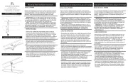
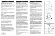
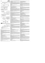
3
4
6
1
1. To assemble shade slide decorative ring (2) over glass shade (3) and
secure ring by tightening set screw with allen key
2. Place glass shade (3) and ring (2) over led assembly (1)
3. Slide center ring (4) over LED assembly (1)
4. Place decorative ring (6) over glass shade (5) and secure ring by
tightening set screw with allen key
5. Place glass shade (5) and ring (6) over led assembly (1)
6. Secure end cap (8) using final (7)
7. Go to the next page for mounting instructions
2
5
1. Para ensamblar la pantalla, deslice el anillo decorativo (2) sobre la
pantalla de vidrio (3) y asegure el anillo apretando el tornillo de
fijación con una llave Allen.
2. Coloque la pantalla de vidrio (3) y el anillo (2) sobre el conjunto de
LED (1).
3. Deslice el anillo central (4) sobre el conjunto de LED (1).
4. Coloque el anillo decorativo (6) sobre la pantalla de vidrio (5) y
asegure el anillo apretando el tornillo de fijación con una llave Allen.
5. Coloque la pantalla de vidrio (5) y el anillo (6) sobre el conjunto de
LED (1).
6. Asegure la tapa del extremo (8) usando el extremo (7)
7. Vaya a la página siguiente para obtener instrucciones de montaje.
Realice las conexiones eléctricas desde el cable de suministro a los
cables conductores del dispositivo. Consulte la hoja de instrucciones
(Instrucciones de cableado I.S. para atenuador LED de 0 a 10 voltios) y
siga todas las instrucciones para realizar todas las conexiones de
cableado necesarias. Luego consulte esta hoja para completar la
instalación de este dispositivo.
Effectuez les connexions électriques du fil d'alimentation aux fils conducteurs
du luminaire. Reportez-vous à la feuille d'instructions (Instructions de câblage
I.S. pour variateur LED 0-10 volts) et suivez toutes les instructions pour
effectuer toutes les connexions de câblage nécessaires. Revenez ensuite à
cette fiche pour finaliser l'installation de ce luminaire.
1. Pour assembler l'abat-jour, faites glisser l'anneau décoratif (2) sur l'abat-
jour en verre (3) et fixez l'anneau en serrant la vis de réglage avec la clé
Allen.
2. Placez l'abat-jour en verre (3) et l'anneau (2) sur l'ensemble LED (1).
3. Faites glisser l'anneau central (4) sur l'ensemble LED (1).
4. Placez l'anneau décoratif (6) sur l'abat-jour en verre (5) et fixez l'anneau
en serrant la vis de réglage avec la clé Allen.
5. Placez l'abat-jour en verre (5) et l'anneau (6) sur l'ensemble LED (1).
6. Fixez l'embout (8) à l'aide de la finale (7).
7. Passez à la page suivante pour les instructions de montage
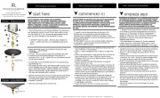
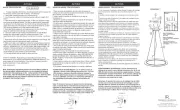
7
8
4. Slip wire through threaded nipple and thread nipple onto last stem
installed
4. Deslice el cable a través del niple roscado y enrosque el niple en el último
vástago instalado.
4. Glissez le fil à travers le raccord fileté et vissez le raccord sur la dernière
tige installée.
T24 JA8-2016

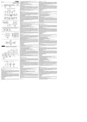
DRAWING 2 - MOUNTING
DRAWING 3 - MOUNTING
B
A
1
2
H
J
S
[Detail 1]
1
HOOK INSPECTION
CABLE TO MOUNTING STRAP.
HOOK
J
F
C
H
S
HINKLEY ley.com 33000 Pin Oak Parkway, Avon Lake, OH 44012 800.446.5539 / 440.653.5500 hink
C
screw (2) from the the side of canopy - DRAWING see 3. After
they are removed the mounting plate can be removed.
2. Now take mounting plate (1) and attach it to the junction box
(J) using two 8-32 screws NOT PROVIDED.
NOTE: The mounting plate has elongated holes that can be 6
used as additional anchor points. It is recommended that these
additional anchor points be used. Make sure to use appropriate
hardware for the material the mounting plate will be attached
too
3. To assemble fixture it is necessary to first remove the
threaded nipple(S) from the canopy (C) - see Drawing 1.
4. This is accomplished by removing the hex nut (N) and lock
washer (L) from the threaded portion of the nipple inside the
canopy
5. Now take nipple and thread it onto the top of the last stem
installed on the fixture. See assembly instructions Drawing 2.
6. Next take canopy and attach it to the stem. Using nuts (N)
and lock washers (L) removed earlier. Note: Please make sure
the square tube does not rotate against the canopy when
assembling
7. Now with assistance take the assembled fixture and lift it up
to the ceiling and using the hook on the end of inspection cable
(I), attached to the inside of canopy (C), hook it into the
mounting plate (1). Now slowly release the fixture until it is
safely hanging from the inspection cable - see DETAIL 1.
NOTE: It is still recommend that an assistant be used to support
fixture during this process.
8. Make all necessary electrical connections between the driver
and junction box following instruction sheet (IS18) provided.
9. To mount canopy (C) to ceiling, align holes (H) in the canopy
with holes (B) in mounting plate (1) and thread screws in
removed earlier.
10. Wiring and installation is complete and power can be
restored.
ocho tornillos (2) del costado de la cubierta; consulte el DIBUJO
3. Después de retirarlos, se puede quitar la placa de montaje.
2. Ahora tome la placa de montaje (1) y fíjela a la caja de
conexiones (J) usando dos tornillos 8-32 NO
PROPORCIONADOS.
NOTA: La placa de montaje tiene 6 orificios alargados que se
pueden utilizar como puntos de anclaje adicionales. Se
recomienda utilizar estos puntos de anclaje adicionales.
Asegúrese de utilizar el hardware adecuado para el material al
que también se unirá la placa de montaje.
3. Para ensamblar el accesorio, primero es necesario quitar la
boquilla roscada (S) de la cubierta (C); consulte el Dibujo 1.
4. Esto se logra quitando la tuerca hexagonal (N) y la arandela
de seguridad (L) de la parte roscada de la boquilla dentro de la
cubierta.
5. Ahora tome la boquilla y enrósquela en la parte superior del
último vástago instalado en el dispositivo. Ver instrucciones de
montaje Dibujo 2.
6. Luego tome el dosel y fíjelo al tallo. Usando tuercas (N) y
arandelas de seguridad (L) que se quitaron anteriormente. Nota:
asegúrese de que el tubo cuadrado no gire contra el dosel al
ensamblar
7. Ahora, con ayuda, tome el dispositivo ensamblado, levántelo
hasta el techo y, usando el gancho en el extremo del cable de
inspección (I), sujeto al interior de la cubierta (C), engánchelo en
la placa de montaje (1). Ahora suelte lentamente el dispositivo
hasta que cuelgue de forma segura del cable de inspección;
consulte el DETALLE 1. NOTA: Aún así, se recomienda utilizar
un asistente para sostener el dispositivo durante este proceso.
8. Realice todas las conexiones eléctricas necesarias entre el
controlador y la caja de conexiones siguiendo la hoja de
instrucciones (IS18) proporcionada.
9. Para montar la cubierta (C) en el techo, alinee los orificios (H)
en la cubierta con los agujeros (B) en la placa de montaje (1) y
enrosque los tornillos que retiró anteriormente.
10. El cableado y la instalación están completos y se puede
restablecer la energía.
huit vis (2) sur le côté de
qu'elles sont retirées, la
2. Prenez maintenant la
boîte de jonction (J) à l'a
REMARQUE : La plaqu
qui peuvent être utilisés
supplémentaires. Il est r
d'ancrage supplémentai
approprié pour le matéri
sera également fixée.
3. Pour assembler le lum
d'abord le raccord fileté
4. Ceci est accompli en
rondelle de blocage (L)
l'intérieur de l'auvent.
5. Prenez maintenant le
la dernière tige installée
montage dessin 2.
6. Prenez ensuite le dai
écrous (N) et des ronde
Remarque : Veuillez vou
pas contre l'auvent lors
7. Maintenant, avec de l
soulevez-le jusqu'au pla
l'extrémité du câble d'ins
(C), accrochez-le à la pl
maintenant lentement le
en toute sécurité au câb
REMARQUE : Il est touj
assistant pour soutenir l
8. Effectuez toutes les c
entre le pilote et la boîte
d'instructions (IS18) fou
9. Pour monter l'auvent
l'auvent avec les trous (
les vis retirées précédem
10. Le câblage et l’insta
être rétabli.

Wiring
Instructions for 0-10 volt LED dimmer
start here
Instrucciones de cableado para atenuador LED de 0-10 voltios
commencez ici
Instructions de câblage pour gradateur LED 0-10 volts
empezar aquí
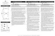
J
WIRES FROM
DIMMER
SUPPLY WIRES
FROM
JUNCTION BOX
Your fixture is designed so it can use a standard incandescent
dimmer, Or a 0-10 volt LED dimmer. If a 0-10 volt LED dimmer is
used, it may be necessary to have additonal wiring installed from the
dimmer switch to the fixture. Consulting an electrician will be
necessary.
Su luminaria está diseñada para que pueda usar un atenuador
incandescente estándar o un atenuador LED de 0-10 voltios. Si se utiliza
un atenuador LED de 0-10 voltios, puede ser necesario instalar cableado
adicional desde el interruptor atenuador hasta la luminaria. Consultar a un
electricista será
DIMMER
DRAWING 1
SWITCH
D
B
W
G
P
1. If using the optional 0-10 volt dimmer there will be four wires exiting
the junction box. (B) Black [+], (W) White [-], wirng are for the 120 /
277 voltage. The (G) Gray {-} and (P) Purple {+} are for the 0-10/Pink
volt wires from the dimmer (D) - see Drawing 1.
2. correspondingThe fixture has four wires of colors. When make the
wire connections follow the chart below.
G
B
W
P
1. Si usa el atenuador opcional de 0-10 voltios, habrá cuatro cables
saliendo de la caja de conexiones. (B) Negro [+], (W) Blanco [-], el
cableado es para el voltaje 120/277. El (G) Gris/Rosa {-} y (P) Púrpura
{+} son para los cables de 0-10 voltios del atenuador (D) - vea el Dibujo
1.
2. El accesorio tiene cuatro cables de colores correspondientes. Cuando
realice las conexiones de los cables, siga la tabla a continuación.
Negro (B) de la caja de empalmes (J) conectado a Negro (B) del
accesorio. Blanco (W) de la caja de empalmes (J) cableado a Blanco
(W) del accesorio. Gris/rosa (G) desde la caja de empalmes (J)
cableado a gris/rosa (G) desde la lámpara. Púrpura (P) desde la caja de
empalmes (J) conectado a Púrpura (P) desde el accesorio.
USO INCANDESCENTE DEL DIMMER:
Si usa un atenuador incadescente, siga las instrucciones del fabricante.
NOTA: ASEGÚRESE DE TAPAR EL CABLE GRIS/ROSA Y PÚRPURA
DEL APARATO DENTRO DEL TOLDO. SI NO ESTÁN TAPADOS,
PUEDEN HACER UN CORTOCIRCUITO Y CAUSAR LA FALLA DEL
APARATO
Votre luminaire est conçu pour pouvoir utiliser un variateur à incandes-
cence standard ou un variateur LED 0-10 volts. Si un gradateur LED
0-10 volts est utilisé, il peut être nécessaire d'avoir un câblage supplé-
mentaire installé entre le variateur et le luminaire. Consulter un
électricien sera
1. Si vous utilisez le gradateur 0-10 volts en option, quatre fils sortiront
de la boîte de jonction. (B) Noir [+], (W) Blanc [-], le câblage est pour la
tension 120/277. Le (G) Gris/Rose {-} et (P) Violet {+} sont pour les fils
0-10 volts du gradateur (D) - voir Dessin 1.
2. Le luminaire a quatre fils de couleurs correspondantes. Lorsque vous
effectuez les connexions des fils, suivez le tableau ci-dessous.
Noir (B) de la boîte de jonction (J) câblé au noir (B) du luminaire . Blanc
(W) de la boîte de jonction (J) câblé au blanc (W) du luminaire. Gris/rose
(G) de la boîte de jonction (J) câblé au gris/rose (G) du luminaire. Violet
(P) de la boîte de jonction (J) câblé au violet (P) du luminaire.
UTILISATION INCANDESCENTE DU DIMMER:
Si vous utilisez un variateur à incandescence, suivez les instructions du
fabricant.
REMARQUE : ASSUREZ-VOUS DE COUPER LE FIL GRIS/ROSE ET
VIOLET DE L'APPAREIL À L'INTÉRIEUR DE L'AUVENT. S'ILS NE
SONT PAS LIMITÉS, ILS PEUVENT COURT-CIRCUITER ET CAUSER
L'ÉCHEC DE L'APPAREIL
driver
wires to LEDS
red
blue/black
Black (B) from junction box (J) wired to Black (B) from
fixture . White (W) from junction box (J) wired to White (W)
from fixture. Gray/Pink (G) from junction box (J) wired to Gray/
pink (G) from fixture. Purple (P) from junction box (J) wired
to Purple (P) from fixture.
Connect ground wire from fixture to ground screw on mounting
hardware
INCANDESCENT DIMMER USAGE:
If using an incadescent dimmer follow manufactures instructions.
NOTE: MAKE SURE TO CAP OFF THE GRAY AND /PINK
PURPLE WIRE FROM THE FIXTURE INSIDE THE CANOPY. IF
THEY ARE NOT CAN SHORT CAPPED THEY OUT AND
CAUSE
THE FIXTURE TO FAIL.
Product specificaties
| Merk: | Fredrick Ramond |
| Categorie: | Lamp |
| Model: | Cy FR41486BK |
Heb je hulp nodig?
Als je hulp nodig hebt met Fredrick Ramond Cy FR41486BK stel dan hieronder een vraag en andere gebruikers zullen je antwoorden
Handleiding Lamp Fredrick Ramond
16 April 2025

16 April 2025
16 April 2025

16 April 2025
16 April 2025
16 April 2025
16 April 2025
16 April 2025
16 April 2025
16 April 2025
Handleiding Lamp
- Eurolite
- Maul
- Craftmade
- Paulmann
- Xiaomi
- Duronic
- Vimar
- Hilti
- Jinbei
- Eminent
- Mission
- Graphite
- Gembird
- Black Diamond
- NUVO
Nieuwste handleidingen voor Lamp
13 September 2025

13 September 2025
12 September 2025
12 September 2025
12 September 2025
8 September 2025
8 September 2025
8 September 2025

6 September 2025
5 September 2025