Valcom VIP-801A Handleiding
Valcom Intercomsysteem VIP-801A
Bekijk gratis de handleiding van Valcom VIP-801A (3 pagina’s), behorend tot de categorie Intercomsysteem. Deze gids werd als nuttig beoordeeld door 58 mensen en kreeg gemiddeld 4.7 sterren uit 8 reviews. Heb je een vraag over Valcom VIP-801A of wil je andere gebruikers van dit product iets vragen? Stel een vraag
Pagina 1/3
1 947767
ISSUE 3
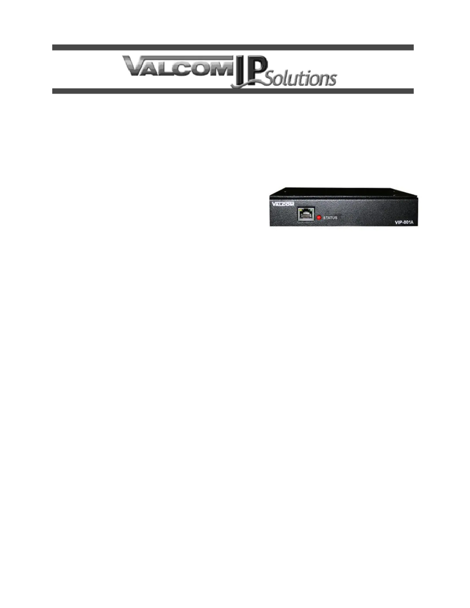
VIP-A, VIP-801A- 801V4
NETWORK AUDIO PORT
INTRODUCTION
The VIP-801A and VIP-801A- Network Audio V4
Ports enable voice access to a single zone of one-
way paging over an IP network, allowing page
zones to be extended anywhere network
connectivity is available. The VIP-801A can be
programmed as a SIP (Session Initiation Protocol)
device for connectivity to virtually any Voice over IP
(VoIP) telephone system.Both models are identical
in t, form and function.
SPECIFICATIONS
Features
•1 Audio Input
•2 Audio Outputs
•2 Form C Relays
•1 Contact Closure Input
•1 SIP identity for registering to a VoIP telephone
system
•-jack for network connection RJ45
•Front panel activity LED
•Provides audio for up to 40 Valcom one-way
amplied speaker assemblies
•AUX audio input via RCA jack
•Contact closure or VOX operation of audio input
•Removable screw terminal connectors provided
for audio and relay interfaces
•AUX input audio mutes during page
•Output control contact closure provided during
paging output
•Compatible with - or 70-Volt ampliers 25
•Barrel jack for optional DC power
•Power over Ethernet (PoE) 802.3af compatible
Dimensions/Weight
• H x 6.13" W x 5.25" D 1.38”
(3.50cm H x 15.6cm W x 13.33cm D)
•Weight: 1.25 lbs. (0.57 kg)
Nominal Specications
Input Impedance: 600 Ohms
Input Level: -10dBm nominal
Voice Switch Sensitivity: -21dBm
AUX Input Impedance: 8 to 600 Ohms
AUX Input Level: -10dBm nominal
Output Impedance: 50 Ohms
Output Level: - 10dBm nominal
Relay Current: 1 Amp @ 24VDC
Nominal Power Requirements
Via rear panel barrel connector:
Voltage: 24VDC
Current: 3mA 25
Via 802.3af PoE Ethernet Switch:
802.3af: Class 3
Environment
Temperature: 0 to +40° C
Humidity: 0 to 85% non-precipitating
Product specificaties
| Merk: | Valcom |
| Categorie: | Intercomsysteem |
| Model: | VIP-801A |
Heb je hulp nodig?
Als je hulp nodig hebt met Valcom VIP-801A stel dan hieronder een vraag en andere gebruikers zullen je antwoorden
Handleiding Intercomsysteem Valcom

13 Maart 2026
11 Februari 2026
11 Februari 2026
11 Februari 2026
10 Februari 2026
10 Februari 2026
10 Februari 2026
10 Februari 2026
9 Februari 2026
9 Februari 2026
Handleiding Intercomsysteem
Nieuwste handleidingen voor Intercomsysteem
10 Maart 2026
10 Maart 2026
4 Maart 2026
4 Maart 2026
4 Maart 2026
3 Maart 2026
30 Januari 2026
10 Januari 2026
8 Januari 2026
8 Januari 2026