Murr Elektronik MB Cap 20/24 Handleiding
Murr Elektronik UPS MB Cap 20/24
Bekijk gratis de handleiding van Murr Elektronik MB Cap 20/24 (17 pagina’s), behorend tot de categorie UPS. Deze gids werd als nuttig beoordeeld door 67 mensen en kreeg gemiddeld 4.7 sterren uit 3 reviews. Heb je een vraag over Murr Elektronik MB Cap 20/24 of wil je andere gebruikers van dit product iets vragen? Stel een vraag
Pagina 1/17
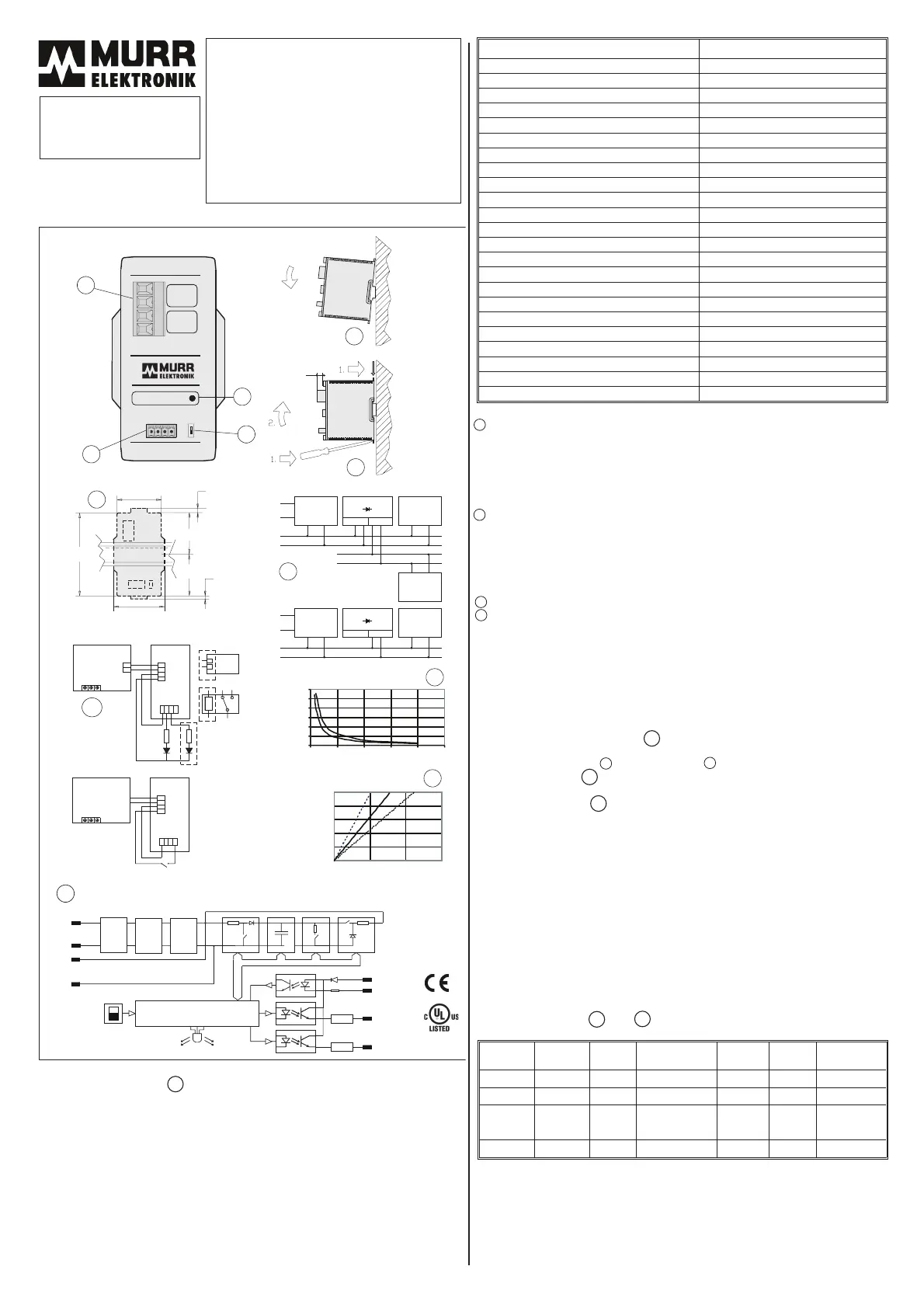
1.Gerätebeschreibung
PufferkondensatorenwerdenunternormalenBedingungenaufgeladen(indemsieeinehöhere
Spannungverwenden,wirdauchdiehöhedergespeichertenEnergiegesteigert).InFolge
eintretenderStörungenderHauptspannung,wirddieseEnergiebenötigt,umdieVerbraucherzu
versorgen.DieÜberbrückungszeitfürStörungenderHauptspannungbeträgtmehrals200ms
mit20APufferstromund24VDC.DenStatistikenzurFolgeistdieseZeitlanggenugummitmehr
als80%SicherheitfürdieungebrocheneStromversorgungderVerbraucherzusorgen.
DiesesProduktistfürdieVerwendunginUmgebungenmitVerschmutzungsgrad2und
überspannungskategorieIIoderIvorgesehenunddarfnurindiesenUmgebungeneingesetzt
werden.
3.Ausrüstung
Ausgangs-/Eingangsklemme:
Leitungsart
Starr4mm²/11AWG
Flexibel4mm²/11AWG
FlexibelmitAdernendhülseohne/mitKunststoffhülse4mm²/11AWG
AdernendhülsemüsseneineMindestlängehaben
≥10mm
Anzugsmoment:0,5-0,6Nm/5-7lb.in.
BitteLeitungenmitmindestens60/75°CTemperaturbeständigkeitverwenden.
Signalklemme:
Leitungsart
Starr0,25-1,5mm²/23-16AWG
Flexibel0,25-1,5mm²/23-16AWG
FlexibelmitAdernendhülseohne/mitKunststoffhülse1,5mm²/16AWG
AdernendhülsemüsseneineMindestlängehaben
≥10mm
Anzugsmoment:0,4Nm/3,5lb.in.
BitteLeitungenmitmindestens60/75°CTemperaturbeständigkeitverwenden.
PufferVerfahren:A(Uin=-1VDC(werkseitigeingestellt)oderB(<22,5VDC)
Betriebsanzeige:ZweifarbigeLED(sieheTabelle“Betriebszustände”)
4.Einbauart
DasPuffermodulmußsoeingebautwerden,daßdieVerlustwärmeungehindertabgeführtwird.
DadurchverbessertsichdieGesamtzuverlässigkeit,undeinfehlerfreierBetriebwirdübereinen
längerenZeitraumgewährleistet.DieKühlungdesPuffermodulserfolgtdurchnatürliche
Luftzirkulation.BeimEinbauistmöglichstvielPlatzfürdieLuftzirkulationzulassen.Esistzu
beachten,daßdieTemperaturoberhalbderGeräteca.25°Chöheristalsunterhalb.Als
UmgebungstemperaturderGerätegiltdieTemperaturdirektunterhalbdesGerätes.Istdie
Luftzirkulationbeschränkt,mußzwangsbelüftetwerden.DerEinbauplatzmußden
BedingungenderEN60950-1Punkt4.7und4.6.1genügen.GehäuseschutzklasseIP20(EN
60529).
5.Einbau,Befestigungslöcher
DieSchienemußsobefestigtwerden,daßsiesichbeimEin-oderAusbaudesGerätesnicht
verdreht.Einbauanweisung,Ausbauanweisung.
6.Inbetriebnahme
DasPuffermodulistalssolchesgebrauchsfertig;sieheAnschlußmöglichkeitenimAnhang.
7.Signalanschlüsse
Signalausgänge:
A=Aktiv:niederohmigwährenddesPufferbetriebs.
R=Bereit:niederohmigwennPuffervollständigaufgeladenist
Strommax.15-20mA(interneStrombegrenzung),Spannungsabfall1-3,5VDC.
Signaleingang:
I=Sperrung:fallendesEingangssignalleitetGeräteabschaltungundZwangsentladungder
Pufferkondensatorenein.
Strom1,5-2mA,sinkend
SignalausgängeundSteuereingangsindDauerkurzschluss-,Leerlauf-undÜberlast-fest.
Anmerkung:Sperrmodusbleibtanfür2minutennachaktivierung.
8.PufferVerfahren/Buffermodes:
ModeA:Eingangsspannung-1VDC;
PufferungerfolgtbeiSpannungsabfallschnellerals0,5V/sundmehrals1VDC.DieSpannung
wirdaufdiesemNiveaugehalten.
ModeB:fest22,5VDC;
PufferungabKlemmenspannung<22,5VDC;Spannungwirdauf22,5VDCgehalten.
9.Betriebszuständeund
Betriebs-
zustände
StromZeitStatusLEDAusgang
‘Aktiv’
Ausgang
‘Bereit’
Puffer
Kondensator
Ladebetrieb<500mA20-45sgrün/blinkt2,5Hzsperrtsperrtlädtauf
Leerlauf<85mA-grün/leuchtetsperrtleitetvoll
Pufferbetrieb0-20A
siehe
Diagrammrot/leuchtetleitetsperrtentlädt
Sperrbetrieb<85mA120sgrün0,1s/1ssperrtsperrtistentladen
10.Normen
Sicherheit:EN60950-1,UL508,SELV
EMV:EN61000-6-2
EN61000-6-3
EN55022classB
Änderungenvorbehalten.
LesenSiedieseBedienungsanleitungvor
EinbauundGebrauchdesPuffermoduls
aufmerksamdurch,damitSiedie
EigenschaftendesPuffermodulsnutzen
können.DasPuffermodulenthält
Eigenschaften,dieIhnenzumehr
ZuverlässigkeitinIhremSystemverhelfen.
BewahrenSiedieseAnleitungfüreinen
möglichenspäterenGebrauchauf.
MBCap20/24
Art.Nr.85394
BEDIENUNGSANLEITUNG
2.TechnischeSpezifikationen,Art.Nr.85394
V1.2
Nennspannung
24VDC(SELV/PELV)
Spannungsbereich
23-30VDC
Nennstrom
<85mA/Leeflauf,<500mALadevorgang
Verpolungschutz
ja
SchutzvorSpannungsspitzen
<35VDC
Ladeverzögerung
<100ms
Ladezeit
20-45s
Ladestrom
<500mA
Ausgangsspannung
24VDC
Spannungsbereich
22-28VDC
Pufferspannung
Uin-1VDCoder<22,5VDC
Nennausgangsstrom
20A
Strombegrenzung
26A
Pufferzeit
0,2s/20A/24VDC-4s/1A/24VDC
Leistungsaufnahme
1,7W/bereit
Wirkungsgrad
>95%/20A
Restwelligkeit
<200mV
rms
Parallelschaltbarkeit
möglich
RelativeFeuchtigkeit
5-95%,keineKondensation
Betriebstemperatur
0°C-+55°C
Lagertemperatur
-25°C-+85°C
Gehäuseschutzklasse,Gehäuse,EN60529
IP20
AbmessungenBxHxTxTA;Gewicht
62x115x145x20mm;0,66kg
Ladezeit
Ladezustand
Ladezeit/s
min.typ.max.
100%
80%
60%
0%
40%
20%
020
40
0
1
2
3
4
5
6
0510152025
Pufferzeit
Zeit/s
min.
typ.
5
6
8
7
11
54
115
2
57
58
5
62
1
2
3
4
9
12
10
TA
Output
+
-
Ready:
Charging:
20A
+
-
Input
DC23-30V
ART.NO.85394
Discharging:
A
R
I
A
BUFFERMODE
R
I
+
GREENblinking
GREENcontinuous
RED
MBCap
A
B
AUin-1V
B22.5V
-Inhibit
-Ready
-Active
AC
Ausgang
Eingang
Versorgung
PufferGerät/e
Ungepufferte
Lasten
Art.No.85394
Gepufferte
Lasten
Gepufferte
Lasten
Art.No.85394
Ausgang
Eingang
>2kOhm
R>2kOhm
+ARI
Versorgung
PufferGerät/e
DC-nichtStabilisiert
DC-Stabilisiert
AC
+
+
DC-Stabilisiert
Programmierbare
Steuerung
Eingang
GND
Spulenwiderstand
Relais
+ARI
+
+
R
AC
Versorgung
LED
AC
ON/OFF
Puffer
Gerät
LNPE
LNPE
+
+
-
-
-
-
-
-
+
-
+
-
+
-
+-+-
+
-
+
-
+
+
-
-
+
-
Versorgung
Puffer
Gerät
Verpolungs-
schutz
Einschalt-
strom-
begrenzer
Entkopplung
Gepuffert/
Ungepuffert
LadegerätPuffer-
kondensator
Puffer-
kondensator
Abschaltung
Puffern
Eingang
Ausgang
Schwellspannungs
Einstellung
Steuerelektronik
Ein-/Ausgangsspannungs
Kontrolle
Uin-1V
22.5V
Strom-
begrenzung
Strom-
begrenzung
15mA
15mA
15kohm
rot
grün
Zustandsanzeige
Max.35VDC
Sperrung
+
Active
Bereit
0
525
20
10
15
Strom/A
0
1
2
3
4
5
6
E222272
1VD7
IND.CONT.EQ
10
1
2
3
4
7
5
6
8
9
11
12
Product specificaties
| Merk: | Murr Elektronik |
| Categorie: | UPS |
| Model: | MB Cap 20/24 |
Heb je hulp nodig?
Als je hulp nodig hebt met Murr Elektronik MB Cap 20/24 stel dan hieronder een vraag en andere gebruikers zullen je antwoorden
Handleiding UPS Murr Elektronik

2 Februari 2024
2 Februari 2024
Handleiding UPS
Nieuwste handleidingen voor UPS
14 April 2026
5 April 2026
5 April 2026
31 Maart 2026
26 Maart 2026
26 Maart 2026
26 Maart 2026
23 Maart 2026
13 Maart 2026
13 Maart 2026