Gewiss GW90884 Handleiding


Lees hieronder de 📖 handleiding in het Nederlandse voor Gewiss GW90884 (3 pagina's) in de categorie Deur-/raamsensor. Deze handleiding was nuttig voor 41 personen en werd door 2 gebruikers gemiddeld met 4.5 sterren beoordeeld

Pagina 1/3
CHORUS IT FREN
ITALIANO
- La sicurezza dell’apparecchio è garantita solo con l’adozione delle istruzioni di sicu-
rezza e di utilizzo; pertanto è necessario conservarle. Assicurarsi che queste istruzio-
ni siano ricevute dall’installatore e dall’utente finale.
- Questo prodotto dovrà essere destinato solo all’uso per il quale è stato espressamen-
te concepito. Ogni altro uso è da considerarsi improprio e/o pericoloso. In caso di
dubbio contattare il SAT Servizio Assistenza Tecnica GEWISS.
- Il prodotto non deve essere modicato. Qualsiasi modica annulla la garanzia e può
rendere pericoloso il prodotto.
- Il costruttore non può essere considerato responsabile per eventuali danni derivati da
usi impropri, erronei e manomissioni del prodotto acquistato.
- Punto di contatto indicato in adempimento ai ni delle direttive e regolamenti UE
applicabili:
GEWISS S.p.a. Via A. Volta, 1 - 24069 Cenate Sotto (BG) - Italy
Tel.: +39 035 946 111 - qualitymarks@gewiss.com
Il simbolo del cassonetto barrato, ove riportato sull’apparecchiatura o
sulla confezione, indica che il prodotto alla ne della propria vita utile deve
essere raccolto separatamente dagli altri rifiuti. AI termine dell’utilizzo,
l’utente dovrà farsi carico di conferire il prodotto ad un idoneo centro di
raccolta dierenziata oppure di riconsegnarlo al rivenditore all’atto
dell’acquisto di un nuovo prodotto. Presso i rivenditori con superficie di vendita di al-
meno 400 m² è possibile consegnare gratuitamente, senza obbligo di acquisto, i
prodotti da smaltire con dimensioni inferiori a 25 cm. L’adeguata raccolta dierenziata
per l’avvio successivo dell’apparecchiatura dimessa al riciclaggio, al trattamento e allo
smaltimento ambientalmente compatibile contribuisce ad evitare possibili eetti nega-
tivi sull’ambiente e sulla salute e favorisce il reimpiego e/o riciclo dei materiali di cui è
composta l’apparecchiatura. GEWISS partecipa attivamente alle operazioni che favori-
scono il corretto reimpiego, riciclaggio e recupero delle apparecchiature elettriche ed
elettroniche
CONTENUTO DELLA CONFEZIONE
La confezione di fornitura del sensore di luminositĂ  KNX contiene i seguenti com-
ponenti:
N.1 Dispositivo sensore di luminositĂ  KNX
N.2 Fascette metalliche
N.1 Manuale di installazione
IN BREVE
Il sensore di luminosità misura l’intensità dell’illuminazione e trasferisce il valore
al sistema KNX.
Dispone di 6 oggetti di comunicazione in uscita di tipo on/off associabili a soglie
impostabili e di porte logiche AND/OR addizionali.
Nell’involucro del dispositivo è alloggiato il sensore e l’elettronica per il collega-
mento del bus KNX (figura A).
FUNZIONI
• Rilevazione luminosità:
l’intensità luminosa è misurata tramite il relativo sensore.
• Uscite di commutazione:
3 oggetti di comunicazione di tipo on/off per funzione crepuscolare (fino a 1000
lux) e 3 per funzione di sensore luminositĂ  (1-99 Klux), associabili a soglie impo-
stabili (i valori di soglia possono essere impostati attraverso parametri o tramite
oggetti di comunicazione).
• Operazioni logiche:
sono disponibili 8 porte AND e 8 porte OR, ciascuna delle quali supporta un
massimo di quattro ingressi. I valori delle uscite di commutazione associate alle
funzioni crepuscolare e di sensore luminositĂ  possono essere utilizzati diretta-
mente come ingressi logici. L’uscita di ciascuna porta logica può generare l’invio
di un oggetto di comunicazione da 1bit o due oggetti da 1byte.
INSTALLAZIONE
ATTENZIONE: l’installazione del dispositivo deve essere effettuata
esclusivamente da personale qualificato, seguendo la normativa vi-
gente e le linee guida per le installazioni KNX/EIB.
AVVERTENZE PER L’INSTALLAZIONE KNX/EIB
1. La lunghezza della linea bus tra il sensore di luminosità KNX e l’alimentatore
non deve superare i 350 metri.
2. La lunghezza della linea bus tra il sensore di luminositĂ  KNX e il piĂš lontano
dispositivo KNX/EIB da comandare non deve superare i 700 metri.
3. Per evitare segnali e sovratensioni non voluti, non dar vita se possibile a circuiti
ad anello.
4. Mantenere una distanza di almeno 4 mm tra i cavi singolarmente isolati della
linea bus e quelli della linea elettrica (figura B).
5. Non danneggiare il conduttore di continuità elettrica della schermatura (gura C).
ATTENZIONE: i cavi di segnale del bus non utilizzati e il conduttore di
continuitĂ  elettrica non devono mai toccare elementi sotto tensione o
il conduttore di terra!
AVVERTENZE PER L’INSTALLAZIONE
L’installazione, l’ispezione, la messa in funzione e l’individuazione/risoluzione di
guasti del sensore di luminosità devono essere eseguiti solo da personale qualicato.
Il dispositivo è concepito esclusivamente per un uso appropriato, qualsiasi mo-
difica non appropriata o la non osservanza delle istruzioni d’uso renderà nulla la
garanzia e qualsivoglia reclamo non avrĂ  valore.
Il sensore di luminositĂ  deve essere azionato solamente dopo essere stato corret-
tamente montato e dopo il completamento di tutte le operazioni di installazione e
di start-up e solo nell’ambiente previsto per il suo utilizzo.
CONNESSIONI ELETTRICHE
Per gli schemi di connessione elettriche si vedano gli esempi che seguono.
1. Connettere il filo rosso del cavo bus al morsetto rosso (+) del terminale e il filo
nero al morsetto nero (-).
Al terminale bus si possono collegare fino a 4 linee bus (fili dello stesso colore
nello stesso morsetto) (figura D).
2. Isolare lo schermo, il conduttore di continuitĂ  elettrica e i rimanenti fili bianco
e giallo del cavo bus (nel caso in cui si utilizzi un cavo bus a 4 conduttori), che
non sono necessari.
POSIZIONAMENTO
Per il montaggio scegliere un’ubicazione in cui il sensore di luminosità sia in grado
di rilevare la luce solare senza alcun impedimento. Il sensore non deve essere
ombreggiato dall’edificio o da altri ostacoli quali, ad esempio, da alberi.
Allineare il sensore di luminositĂ  in direzione sud. (figura E)
Il sensore di luminositĂ  deve essere montato in posizione verticale su un muro o
un palo. (figura F)
Il sensore di luminositĂ  deve essere montato in posizione orizzontale. (figura G)
FISSAGGIO DEL SUPPORTO
Il sensore di luminositĂ  viene fornito con un supporto da parete o da palo.
Fissare il supporto verticalmente su di una parete o un palo.
Montaggio a parete: parte piatta sulla parete, parte con collarino sporgente
rivolta verso l’alto. (figura H)
Montaggio su di un palo: parte curva sul palo, collarino rivolto verso il basso.
(figura I)
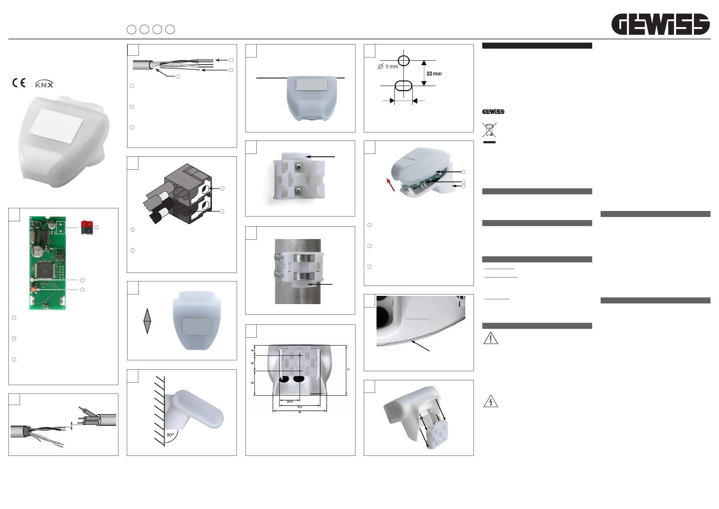
VISTA DELLA PARTE POSTERIORE E SCHEMA DI FORATURA (figura L)
Dimensioni della parte posteriore dell’alloggiamento con staffa (figura M).
Soggetta a modifiche in caso di migliorie.
PREDISPOSIZIONE DEL SENSORE (figura N)
Il coperchio del dispositivo è dotato di innesti a sinistra e a destra lungo il bordo
inferiore.
Rimuovere il coperchio.
Spingere il cavo per la connessione bus attraverso la guarnizione di gomma sul
fondo del sensore e collegare il bus KNX agli appositi morsetti.
MONTAGGIO DEL SENSORE
Chiudere l’alloggiamento ricollocando il coperchio sulla parte inferiore.
Il coperchio deve innestarsi perfettamente a destra e a sinistra, udendo un nitido
“click”.
Accertarsi che il coperchio e la parte inferiore siano effettivamente bloccati
insieme.
Questa figura mostra il sensore chiuso con vista dal basso. (figura O)
Spingere l’alloggiamento da sopra nel supporto fissato.
Le protuberanze presenti sul supporto devono innestarsi a scatto nelle guide
dell’alloggiamento. (figura P)
PROGRAMMAZIONE
PROGRAMMA APPLICATIVO
Il programma applicativo può essere scaricato dal sito www.gewiss.com. Infor-
mazioni dettagliate sui parametri di configurazione e sui loro valori sono contenuti
nel Manuale Tecnico.
PROGRAMMAZIONE INDIRIZZO FISICO
1. Alimentare il dispositivo attraverso il bus.
2. Premere il pulsante di programmazione per predisporre il sensore di luminositĂ 
KNX al caricamento da ETS dell’indirizzo fisico.
Per poter configurare il dispositivo via ETS è sufficiente l’alimentazione bus KNX.
MANUTENZIONE
Il sensore deve essere controllato regolarmente due volte l’anno per individuare
un’eventuale presenza di sporcizia e se necessario deve essere pulito.
Per rimuovere il sensore è sufficiente tirare semplicemente verso l’alto, vincendo
la resistenza del fissaggio.
Non aprire il sensore in caso di pioggia o comunque se dell’acqua può penetrare
all’interno: anche poche gocce possono danneggiare il sistema elettronico.
DATI TECNICI
Contenitore: materiale plastico
Colore: bianco
Montaggio: parete o palo
Grado di protezione: IP44
Dimensioni: 96 × 77 × 118 (L × H × P, mm)
Peso: 150 g
Temperatura di
funzionamento e stoccaggio:
operativa -30…+50°C,
stoccaggio -30…+70°C
Alimentazione: tensione bus KNX
Assorbimento bus KNX: max. 10 mA, con ripple 10%
Connettore dati uscita: standard KNX
BCU tipo: inclusa nel microcontrollore
PEI tipo: 0
Indirizzi di gruppo: max. 254
Allocazioni: max. 255
Oggetti di comunicazione: 117
Range sensore di luminosità: 0…150000 lux
Risoluzione: 1 lux a 0…120 lux
2 lux a 121…1046 lux
63 lux a 1047…52363 lux
423 lux a 52364…150000lux
Precisione: Âą35%
I seguenti standard sono stati presi in considerazione per la valutazione del prodot-
to in termini di compatibilitĂ  elettromagnetica:
Emissioni transienti:
• EN 60730-1:2000 Sezione EMC (23, 26, H23, H26) (categoria soglia: B)
• EN 50090-2-2:1996-11 + A1:2002-01 (categoria soglia: B)
• EN 61000-6-3:2001 (categoria soglia: B)
Resistenza alle interferenze:
• EN 60730-1:2000 Sezione EMC (23, 26, H23, H26)
• EN 50090-2-2:1996-11 + A1:2002-01
• EN 61000-6-1:2004
Il prodotto è stato testato a fronte degli standard sopracitati da un laboratorio
accreditato EMC.
A
1 Morsetto bus KNX
KNX BUS terminal
Borne bus KNX
KNX-Busklemme
2 LED di programmazione KNX
KNX programming LED
LED de programmation KNX
KNX-Programmierled
3 Pulsante di programmazione KNX
KNX push-button for programming
Bouton-poussoir de programmation KNX
KNX-Programmiertaster
1
2
3
Bus
230 V
≥ 4 mm
B
3
1
2
C
1 Cavo bus
Bus cable
Câble bus
Buskabel
2 Conduttore di continuitĂ  elettrica
Electrical continuity conductor
Conducteur de continuitĂŠ ĂŠlectrique
Beidraht
3 Schermatura
Shielding
Blindage
Schirm
D
1 Connessione dispositivo bus
Connection of the BUS device
Connexion dispositif bus
Anschluss Busgerät
2 Connessione cavo bus
Connection of the BUS cable
Connexion câble bus
Anschluss Buskabel
1
2
Sensore luminositĂ  KNX
KNX light intensity sensor
Capteur de luminositĂŠ KNX
Helligkeitsensor KNX
GW 90 884
L
Dimensioni in mm
Dimensions in mm
Dimensions en mm
Abmessungen in mm
Nord
North
Nord
Nord
Sud
South
Sud
SĂźden
E
Muro o palo
Wall or pole
Saillie ou poteau
Wand oder Mast
F
Orizzontale
Horizontal
Horizontale
Horizontale
Waagrecht
G
H
Collarino
Collar
Collier
Bund
I
Collarino
Collar
Collier
Bund
Fissaggio
Fixing
Fixation
Befestigun
O
P
DE
M
Asola 7,5 x 5 mm
Slot 7.5 x 5mm
Fente 7,5 x 5 mm
Verschließbare Önung 7,5 x 5 mm
Schema di foratura
Perforation layout
SchÊma de perçage
Bohrschema
N
1 Innesti del coperchio
Cover connections
Raccords du couvercle
Deckelrasten
2 Scheda PCB
PCB card
Carte PCB
PCB-Platine
3 Parte inferiore dell’alloggiamento
Lower part of the housing
Partie infĂŠrieure du logement
Unterer Gehäuseteil
1
2
3
Sganciare il coperchio e rimuoverlo tirando verso l’alto
Unhook the cover and remove it by pulling upwards
DĂŠcrocher le couvercle et le retirer en tirant vers le haut
Den Deckel aushängen und entfernen, indem man ihn nach unten zieht
+ 139 035 946 11
8.30 - 12.30 / 14.00 - 18.00
lunedÏ á venerdÏ - monday á friday
+39 035 946 260 sat@gewiss.com
www.gewiss.com
24h
Punto di contatto indicato in adempimento ai ni delle direttive e regolamenti UE applicabili:
Contact details according to the relevant European Directives and Regulations:
GEWISS S.p.A. Via A.Volta, 1 IT-24069 Cenate Sotto (BG) Italy tel: +39 035 946 111 E-mail: qualitymarks@gewiss.com
ULTIMA REVISIONE 12/2017 cod. 7.01.8.937.8
IT Seguire le istruzioni e conservarle per la consegna all’utente finale. Evitare qualsiasi uso improprio, manomissioni e modifiche. Rispettare le vigenti norme sugli impianti - Follow the instructions and keep them safe for delivery to the end user. Avoid any misuse, tampering and modifications. Comply with the current regulations regarding the systems - Observer les consignes et les conserver pour la livraison à EN FR
l’utilisateur final. Éviter tout usage impropre, interventions illicites et modifications. Respecter les normes en vigueur sur les installations - Befolgen Sie die Anweisungen und bewahren Sie diese für eine Weitergabe an den Endbenutzer auf.Unsachgemäßer Gebrauch, Manipulationen und Änderungen sind zu vermeiden.Beachten Sie die für die Anlagen geltenden einschlägigen NormenDE
ENGLISH
- Device safety is only guaranteed when the safety and usage instructions are re-
spected, so keep them handy. Make sure these instructions are received by the
installer and end user.
- This product must only be used for the purpose for which it was designed. Any
other form of use should be considered improper and/or dangerous. If you have any
doubts, contact the GEWISS SAT technical support service.
- The product must not be modied. Any modication will annul the warranty and may
make the product dangerous.
- The manufacturer cannot be held liable for any damage if the product is improperly
or incorrectly used or tampered with.
- Contact point indicated for the purposes of fullling the applicable EU directives and
regulations:
GEWISS S.p.a. Via A. Volta, 1 - 24069 Cenate Sotto (BG) - Italy
Tel.: +39 035 946 111 - qualitymarks@gewiss.com
If the crossed-out bin symbol appears on the equipment or packaging, this
means the product must not be included with other general waste at the
end of its working life. The user must take the worn product to a sorted
waste centre, or return it to the retailer when purchasing a new one. Prod-
ucts for disposal can be consigned free of charge (without any new pur-
chase obligation) to retailers with a sales area of at least 400 m², if they measure less
than 25cm. An ecient sorted waste collection for the environmentally friendly dispos-
al of the used device, or its subsequent recycling, helps avoid the potential negative
eects on the environment and people’s health, and encourages the re-use and/or
recycling of the construction materials. GEWISS actively takes part in operations that
sustain the correct salvaging and re-use or recycling of electric and electronic equip-
ment.
PACK CONTENTS
The supply pack of the KNX light intensity sensor contains the following com-
ponents:
1 KNX light intensity sensor device
2 metal hose clamps
1 Installation manual
BRIEFLY
The light intensity sensor measures the intensity of the lighting and communicates
the value to the KNX system.
It has 6 output communication elements of the ON/OFF type (that can be associat-
ed with settable thresholds), and additional AND/OR logic ports.
The device shell houses the sensor and the electronics for connecting the KNX
BUS. (figure A).
FUNCTIONS
• Light intensity detection:
the light intensity is measured by means of the relative sensor.
• Switchover outputs:
3 ON/OFF communication elements with a light sensitive function (up to 1000
lux), and 3 with a light intensity sensor function (1-99 Klux), that can be associ-
ated with settable thresholds (the threshold values can be set via parameters or
communication elements).
• Operazioni logiche:
there are 8 AND ports and 8 OR ports, each supporting up to four inputs. The
values of the switchover outputs associated with the light sensitive and light
intensity sensor functions can be used directly as logic inputs. The output of
each logic port can generate the sending of one communication item of 1 bit, or
two items of 1 byte.
INSTALLATION
ATTENTION: the device must only be installed by qualified personnel,
observing the current regulations and the guidelines for KNX/EIB in-
stallations.
WARNINGS FOR KNX/EIB INSTALLATION
1. The length of the BUS line between the KNX light intensity sensor and the power
supply must not exceed 350 metres.
2. The length of the BUS line between the KNX light intensity sensor and the
furthest KNX/EIB device to be commanded must not exceed 700 metres.
3. To avoid unwanted signals and overvoltages, try not to create ring circuits.
4. Keep a distance of at least 4mm between the individually insulated cables of the
BUS line and those of the electricity line. (figure B).
5. Do not damage the electrical continuity conductor of the shielding. (figure C).
ATTENTION: the unused BUS signal cables, and the electrical conti-
nuity conductor, must never touch live elements or the earth conduc-
tor!
WARNINGS FOR INSTALLATION
Installation, inspection, start-up, and troubleshooting operations on the light inten-
sity sensor must only be carried out by qualified personnel.
The device is designed for a specific, appropriate use, and any inappropriate mod-
ification or failure to observe the user instructions will invalidate both the warranty
and any claims.
The light intensity sensor must only be activated after being correctly assembled
and after completing all the installation and start-up operations, and only within
the sphere of its intended use.
ELECTRIC CONNECTIONS
For the electric connection layouts, refer to the examples below.
1. Connect the red wire of the BUS cable to the red clamp (+) of the terminal, and
the black wire to the black clamp (-).
Up to 4 BUS lines (wires of the same colour in the same clamp) can be connect-
ed to the BUS terminal. (figura D).
2. Insulate the shield, the electrical continuity conductor, and the remaining white
and yellow wires of the BUS cable (when using a 4-conductor BUS cable), as
these are not needed.
POSITIONING
For the assembly, choose a place where the light intensity sensor can detect solar
light without any hindrance. The sensor must not be in the shadow of the building,
or of any other obstacles such as trees and so on.
Position the light intensity sensor so it is facing south. (figure E)
The light intensity sensor must be assembled vertically, on a wall or pole.
(figure F)
The light intensity sensor must be assembled horizontally. (figure G)
FIXING THE SUPPORT
The light intensity sensor is supplied with a surface-mounting support.
Fix the support vertically on a wall or pole.
Surface-mounting: the flat part on the wall, and the part with the protruding
collar facing upwards. (figure H)
Pole-mounting: the curved part on the pole, and the collar facing downwards.
(figure I)
VIEW OF THE REAR PART, AND PERFORATION LAYOUT (figure L)
Dimensions of the rear part of the housing with bracket. (figure M).
Subject to improvement modifications.
PRE-ARRANGEMENT OF THE SENSOR (figura N)
The device cover has connections on the left and right, along the lower edge
(see the figure).
Remove the cover.
Push the BUS connection cable through the rubber gasket on the sensor base,
then connect the KNX BUS to the appropriate clamps.
ASSEMBLING THE SENSOR
Close the housing by replacing the cover on the lower part.
The cover must be well inserted on both the right and the left (you should clearly
hear a “click”).
Check the cover and lower part are well locked together.
This figure shows the closed sensor from below. (figure O)
Push the housing down into the fixed support.
The protrusions on the support must clip into the housing guides. (figure P)
PROGRAMMING
APPLICATION PROGRAM
The application program can be downloaded from the website www.gewiss.com.
Detailed information on the configuration parameters and their values is contained
in the Technical Manual.
PROGRAMMING THE PHYSICAL ADDRESS
1. Power the device via the BUS.
2. Press the programming push-button to prepare the KNX light intensity sensor for
the loading of the physical address from ETS.
To configure the device via ETS, just the KNX BUS power supply is sufficient.
MAINTENANCE
The sensor must be regularly checked (twice a year) for the presence of dirt, and
cleaned if necessary.
To remove the sensor, just pull it upwards (there will be some resistance from
the fixing element).
Do not open the sensor when it is raining, or in any case when water could get
inside it: even just a few drops may damage the electronic system.
TECHNICAL DATA
Container: plastic material
Colour: white
Assembly: wall or pole
Degree of protection: IP44
Dimensions: 96 × 77 × 118 (L × H × D, mm)
Weight: 150 g
Operating and storage
temperature:
operating -30…+50°C /
storage -30…+70°C
Power supply: KNX BUS voltage
KNX BUS Consumption: max. 10 mA, with 10% ripple
Output data connector: KNX Standard
BCU type: included in the micro-controller
PEI type: 0
Group addresses: max. 254
Places: max. 255
Communication elements: 117
Light intensity sensor range: 0…150000 lux
Resolution: 1 lux at 0…120 lux
2 lux at 121…1046 lux
63 lux at 1047…52363 lux
423 lux at 52364…150000 lux
Precision: Âą35%
The following standards were taken into consideration when evaluating the elec-
tromagnetic compatibility of the product:
Transient emissions:
• EN 60730-1:2000 Section EMC (23, 26, H23, H26) (threshold category: B)
• EN 50090-2-2:1996-11 + A1:2002-01 (threshold category: B)
• EN 61000-6-3:2001 (threshold category: B)
Resistance to interference:
• EN 60730-1:2000 Section EMC (23, 26, H23, H26)
• EN 50090-2-2:1996-11 + A1:2002-01
• EN 61000-6-1:2004
The product has been tested on the basis of the above-mentioned standards, by
an EMC-accredited laboratory.
FRANÇAIS
- -La sécurité de l’appareil n’est garantie que si les consignes de sécurité et d’utilisa
tion sont observées ; aussi, s’avère-t-il nécessaire de les conserver. S’assurer que
ces consignes ont été reçues par l’installateur et par l’utilisateur final.
- Ce produit est uniquement destiné à l’usage pour lequel il a été expressément conçu.
Toute autre utilisation est considĂŠrĂŠe comme impropre et/ou dangereuse. En cas de
doute, contacter le service d’assistance technique SAT GEWISS.
- Le produit ne doit pas être modiÊ. Toute modication invalide la garantie et peut
rendre le produit dangereux.
- Le constructeur ne peut ĂŞtre tenu pour responsable des dommages ĂŠventuels dĂŠri-
vant d’un usage impropre, erroné ou bien d’une altération du produit acheté.
- Point de contact indiquĂŠ en application des directives et des rĂŠglementations UE
applicables :
GEWISS S.p.a. Via A. Volta, 1 - 24069 Cenate Sotto (BG) - Italie
TĂŠl. : +39 035 94 61 11 - qualitymarks@gewiss.com
le symbole de la poubelle barrée, là où il est reporté sur l’appareil ou
l’emballage, indique que le produit en fin de vie doit être collecté séparé-
ment des autres déchets. Au terme de la durée de vie du produit, l’utilisa-
teur devra se charger de le remettre Ă  un centre de collecte sĂŠparĂŠe ou
bien au revendeur lors de l’achat d’un nouveau produit. Il est possible de
remettre gratuitement, sans obligation d’achat, les produits à éliminer de dimensions
inférieures à 25 cm aux revendeurs dont la surface de vente est d’au moins 400 m2.
La collecte diérenciée et l’envoi successif de l’appareil en fin de vie au recyclage, au
traitement et à l’élimination compatible avec l’environnement contribue à éviter les
eets négatifs sur l’environnement et sur la santé et favorise le réemploi et/ou le recy-
clage des matières de l’appareil. Gewiss participe activement aux opérations favorisant
le rĂŠemploi, le recyclage et la rĂŠcupĂŠration des appareils ĂŠlectriques et ĂŠlectroniques.
CONTENU DE LA CONFECTION
La confection de fourniture du capteur de luminositĂŠ KNX contient les composants
suivants :
1 Dispositif du capteur de luminositĂŠ KNX
2 Colliers de serrage en mĂŠtal
1 Manuel d’installation
RÉSUMÉ
Le capteur de luminosité mesure l’intensité de l’éclairage et transfère la valeur au
système KNX.
Il dispose de 6 objets de communication en sortie de type ON/OFF associĂŠs Ă  des
seuils rĂŠglables et de portes logiques AND/OR additionnelles.
L’enveloppe du dispositif contient le capteur et l’électronique de liaison du bus KNX.
(gure ).A
FONCTIONS
• Relevé de la luminosité :
l’intensité lumineuse est mesurée à l’aide du capteur correspondant.
• Sorties de commutation :
3 objets de communication de type ON/OFF pour la fonction crépusculaire (jusqu’à
1000 lux) et 3 pour la fonction de capteur de luminositĂŠ (1-99 klux), associĂŠs
Ă  des seuils rĂŠglables (les valeurs de seuil peuvent ĂŞtre imposĂŠes Ă  travers des
paramètres ou des objets de communication).
• Opérations logiques :
8 portes AND et 8 portes OR sont disponibles. Chacune supporte un maximum de
quatre entrĂŠes. Les valeurs des sorties de commutation associĂŠes Ă  la fonction de
capteur crĂŠpusculaire et Ă  la fonction de capteur de luminositĂŠ peuvent ĂŞtre direc-
tement utilisĂŠes comme entrĂŠes logiques. La sortie de chaque porte logique peut
générer l’envoi d’un objet de communication d’un bit ou deux objets d’un octet.
INSTALLATION
ATTENTION: l’installation du dispositif doit uniquement être réalisée par
un personnel qualiÊ, en suivant la rÊglementation en vigueur et les
lignes directrices relatives aux installations KNX/EIB.
CONSIGNES POUR L’INSTALLATION KNX/EIB
1. La longueur de la ligne bus entre le capteur de luminosité KNX et l’alimentateur ne
doit pas dÊpasser 350 mètres.
2. La longueur de la ligne bus entre le capteur de luminositĂŠ KNX et le dispositif KNX/
EIB à commander le plus ÊloignÊ ne doit pas dÊpasser 700 mètres.
3. Afin d’éviter les surtensions et les signaux intempestifs, éviter de créer des circuits
en boucle.
4. Maintenir une distance d’au moins 4 mm entre les câbles individuellement isolés
de la ligne bus et ceux de la ligne Êlectrique. (gure B).
5. Ne pas dÊtÊriorer le conducteur de continuitÊ Êlectrique du blindage. (gure C).
ATTENTION: les câbles de signal du bus non utilisÊs et le conducteur de
continuitĂŠ ĂŠlectrique ne doivent jamais toucher des ĂŠlĂŠments sous ten-
sion ou le conducteur de terre !
CONSIGNES POUR L’INSTALLATION
L’installation, l’inspection, la mise en marche et la recherche et la résolution des
dysfonctionnements du capteur de luminositĂŠ doivent uniquement ĂŞtre exĂŠcutĂŠes par
un personnel qualiÊ.
Le dispositif a exclusivement ÊtÊ conçu pour un usage spÊcique. Toute modication
non appropriée ou l’inobservation des instructions d’utilisation annulera la garantie et
aucune réclamation n’aura de valeur.
Le capteur de luminositÊ doit être uniquement actionnÊ après avoir ÊtÊ correctement
monté et après l’exécution de toutes les opérations d’installation et de démarrage,
uniquement dans l’ambiance prévue pour son usage.
CONNEXIONS ÉLECTRIQUES
Pour les schĂŠmas de connexion ĂŠlectrique, voir les exemples suivants.
1. Connecter le l rouge du câble bus à la borne rouge (+) du terminal et le l noir à
la borne noire (-).
On pourra relier, au terminal bus, jusqu’à 4 lignes bus (fils de même couleur sur la
même borne). (gura D).
2. Isoler le blindage, le conducteur de continuitÊ Êlectrique et les ls blanc et jaune
restants du câble bus (si l’on emploie un câble bus à 4 conducteurs), qui ne sont
pas nĂŠcessaires.
POSITIONNEMENT
Pour le montage, choisir un emplacement oĂš le capteur de luminositĂŠ est en mesure
de relever la lumière solaire sans aucun empêchement. Le capteur ne doit pas être
ombragÊ par le bâtiment ou autres obstacles comme, par exemple, les arbres.
Aligner le capteur de luminositÊ en direction du sud. (gure E)
Le capteur de luminositĂŠ doit ĂŞtre montĂŠ Ă  la verticale en saillie ou sur un poteau.
(gure F)
Le capteur de luminosité doit être monté à l’horizontale. (figura G)
FIXATION DU SUPPORT
Le capteur de luminositĂŠ est fourni avec un support en saillie ou sur poteau.
Fixer le support Ă  la verticale en saillie ou sur un poteau.
Montage en saillie : partie plate sur la paroi, partie avec le collier en saillie dirigĂŠe
vers le haut. (gure H)
Montage sur poteau : partie courbe sur le poteau, collier dirigÊ vers le bas. (gura I)
VUE DE L’ARRIÈRE ET SCHÉMA DE PERÇAGE (figura L)
Dimensions de la paroi arrière du logement avec patte. (gura M).
Sujette à modications pour amÊlioration.
PRÉPARATION DU CAPTEUR (figura N)
Le couvercle du dispositif est ĂŠquipĂŠ de raccords Ă  gauche et Ă  droite le long du bord
infÊrieur (voir gure).
Retirer le couvercle.
Pousser le câble d’alimentation et la connexion du bus à travers le joint en caoutchouc
sur le fond du capteur et raccorder le bus KNX aux bornes correspondantes.
MONTAGE DU CAPTEUR
Refermer le logement en replaçant le couvercle sur la partie infÊrieure.
Le couvercle doit s’enclencher parfaitement à droite et à gauche et fait entendre
un clic net
S’assurer que le couvercle et la partie inférieure sont bien assemblés.
Cette vue du bas illustre le capteur fermÊ. (gura O)
Spingere l’alloggiamento da sopra nel supporto fissato.
Pousser le logement par dessus dans le support xÊ.
Les protubérances du support doivent s’enclencher par déclic dans les guides du
logement. (gura P)
PROGRAMMATION
PROGRAMME D’APPLICATION
Le programme d’application peut être déchargé du site www.gewiss.com. De plus
amples informations sur les paramètres de conguration et sur leurs valeurs sont
reportĂŠes dans le manuel technique.
PROGRAMMATION DE L’ADRESSE PHYSIQUE
1. Alimenter le dispositif Ă  travers le bus.
2. Appuyer sur le bouton-poussoir de programmation pour prĂŠparer le capteur de
luminosité KNX au chargement, depuis l’ETS, de l’adresse physique.
Afin de pouvoir configurer le dispositif via ETS, l’alimentation du bus KNX est suf-
sante.
ENTRETIEN
Le capteur doit être rÊgulièrement contrôlÊ deux fois par an an de dÊtecter la prÊ-
sence de saletĂŠ et le nettoyer au besoin.
Pour retirer le capteur, il sut de tirer simplement vers le haut, en surmontant la
rÊsistance de xation.
Ne pas ouvrir le capteur en cas de pluie ou, pour le moins, si de l’eau peut y pénétrer
: même quelques gouttes peuvent dÊtÊriorer le système Êlectronique.
CARACTÉRISTIQUES TECHNIQUES
BoÎtier : matière plastique
Couleur : blanc
Montage : en saillie ou sur poteau
Indice de protection : IP44
Dimensions : 96 × 77 × 118 (L × H × P mm)
Poids : 150 g
TempĂŠrature de fonctionne-
ment et de stockage :
service -30…+50°C,
stockage -30…+70°C
Alimentation : tension du bus KNX
Absorption du bus KNX : max. 10 mA, avec ondulation ripple 10%
Connecteur de donnĂŠes de
sortie :
standard KNX
BCU type : incluse dans le microcontrĂ´leur
PEI type : 0
Adresses de groupe : max 254
Allocations : max 255
Objets de communication : 117
ntervalle du capteur de
luminositĂŠ :
0…150000 lux
Résolution : 1 lux à 0…120 lux
2 lux à 121…1046 lux
63 lux à 1047…52363 lux
423 lux à 52364…150000 lux
PrĂŠcision : Âą35%
Les standards suivants ont ĂŠtĂŠ pris en compte pour ĂŠvaluer le produit en termes de
compatibilitĂŠ ĂŠlectromagnĂŠtique :
Émissions transitoires :
• EN 60730-1:2000 Section CEM (23, 26, H23, H26) (catégorie de seuil : B)
• EN 50090-2-2:1996-11 + A1:2002-01 (catégorie de seuil : B)
• EN 61000-6-3:2001 (catégorie de seuil : B)
RĂŠsistance aux interfĂŠrences :
• EN 60730-1:2000 Section CEM (23, 26, H23, H26)
• EN 50090-2-2:1996-11 + A1:2002-01
• EN 61000-6-1:2004
Le produit a ĂŠtĂŠ testĂŠ sur les standards citĂŠs par un laboratoire agrĂŠĂŠ CEM.
DEUTSCH
- -Die Sicherheit des Geräts wird nur bei Anwendung der Sicherheits- und Bedienungs
anweisungen garantiert; daher mĂźssen diese aufbewahrt werden. Sicherstellen,
dass der Installateur und der Endbenutzer diese Anweisungen erhalten.
- Dieses Produkt darf nur fĂźr den Einsatz vorgesehen werden, fĂźr den es ausdrĂźcklich
konzipiert wurde. Jeder andere Einsatz ist als unsachgemäß und/oder gefährlich zu
betrachten. Im Zweifelsfall den technischen Kundendienst SAT von GEWISS kon-
taktieren.
- Das Produkt darf nicht umgerĂźstet werden. Jegliche UmrĂźstung macht die Garantie
ungßltig und kann das Produkt gefährlich machen.
- Der Hersteller kann nicht fßr eventuelle Schäden haftbar gemacht werden, die aus
unsachgemäßem oder falschem Gebrauch oder unsachgemäßen Eingrien am er-
worbenen Produkt entstehen.
- Angabe der Kontaktstelle in Übereinstimmung mit den anwendbaren EU-Richtlinien
und -Regelwerken:
GEWISS S.p.a. Via A. Volta, 1 - 24069 Cenate Sotto (BG) - Italy
Tel.: +39 035 946 111 - qualitymarks@gewiss.com
Das Symbol der durchgestrichenen Mßlltonne auf dem Gerät oder seiner
Verpackung weist darauf hin, dass das Produkt am Ende seiner Nutzungs-
dauer getrennt von den anderen Abfällen zu entsorgen ist. Nach Ende der
Nutzungsdauer obliegt es dem Nutzer, das Produkt in einer geeigneten
Sammelstelle fĂźr getrennte MĂźllentsorgung zu deponieren oder es dem
Händler bei Ankauf eines neuen Produkts zu ßbergeben. Bei Händlern mit einer Ver-
kaufsfläche von mindestens 400 m² können zu entsorgende Produkte mit Abmessun-
gen unter 25 cm kostenlos und ohne Kaufzwang abgegeben werden. Die angemesse-
ne Mßlltrennung fßr das dem Recycling, der Behandlung und der umweltverträglichen
Entsorgung zugefßhrten Gerätes trägt dazu bei, mÜgliche negative Auswirkungen auf
die Umwelt und die Gesundheit zu vermeiden und begĂźnstigt den Wiedereinsatz und/
oder das Recyceln der Materialien, aus denen das Gerät besteht. Gewiss beteiligt sich
aktiv an den Aktionen fĂźr die korrekte Wiederverwendung, das Recycling und die RĂźck-
gewinnung von elektrischen und elektronischen Geräten.
PACKUNGSINHALT
Im Lieferumfang des KNX-Helligkeitssensors sind die folgenden Komponenten
enthalten:
1 KNX-Helligkeitssensor
2 Schneckengewinde-Schellen
1 Installationshandbuch
KURZBESCHREIBUNG
Der Helligkeitssensor misst die Lichtstärke und ßbermittelt den Wert an das
KNX-System.
Er verfügt über 6 Ausgangskommunikationsobjekte vom Typ On/O, die mit ein-
stellbaren Schwellen verknßpft werden kÜnnen, und zusätzliche logische AND/
OR-Schnittstellen.
Im Gehäuse der Vorrichtung benden sich der Sensor und die Elektronik fßr den
Anschluss des KNXBusses. (abbildung A).
FUNKTIONEN
• Messung der Helligkeit:
Die Lichtstärke wird durch den entsprechenden Sensor gemesse
• Schaltausgänge:
3 Kommunikationsobjekte vom Typ On/O für die Funktion Dämmerungssensor
(bis 1000 lux) und 3 fĂźr die Funktion Helligkeitssensor (1-99 klux), die mit ein-
stellbaren Schwellen verknĂźpft werden kĂśnnen (die Schwellenwerte kĂśnnen Ăźber
Parameter oder Ăźber Kommunikationsobjekte eingestellt werden).
• Logische Operationen:
Es stehen 8 AND- und 8 OR-Schnittstellen zu VerfĂźgung, von denen jede maximal
vier Eingänge unterstßtzt. Die Werte der mit der Funktionen Dämmerungssensor
und Helligkeitssensor verknßpften Schaltausgänge kÜnnen direkt als logische
Eingänge benutzt werden. Der Ausgang jeder logischen Schnittstelle kann ein
Kommunikationsobjekt mit 1bit oder 2 Objekte mit 1byte senden.
INSTALLATION
ACHTUNG: Die Installation des Geräts darf ausschließlich von Fach-
personal unter Einhaltung der geltenden Vorschriften und der Richtli-
nien fĂźr KNX/EIB-Installationen vorgenommen werden.
HINWEISE FÜR DIE KNX/EIB-INSTALLATION
1. Die Länge der Busleitung zwischen dem KNX-Helligkeitssensor und dem Netzge-
rät darf 350 Meter nicht ßberschreiten.
2. Die Länge der Busleitung zwischen dem KNX-Helligkeitssensor und dem am
weitesten entfernten KNX/EIB-Gerät darf 700 Meter nicht ßberschreiten.
3. Um ungewollte Signale und Überspannungen zu vermeiden, Schleifenbildungen
so weit wie mĂśglich unterlassen.
4. Einen Abstand von mindestens 4 mm zwischen den einzeln isolierten Kabeln der
Busleitung und denen der Stromleitung einhalten. (abbildung B).
5. Non danneggiare il conduttore di continuitĂ  elettrica della schermatura (abbil-
dung ).C
ACHTUNG: Die nicht benutzten Bus-Signalkabel und der Beidraht dĂźr-
fen niemals unter Strom stehende Elemente oder den Erdungsleiter
berĂźhren!
HINWEISE FÜR DIE INSTALLATION
Die Installation, die Inspektion, die Inbetriebnahme und die Fehlersuche/-behebung
des Helligkeitssensors dĂźrfen nur von Fachpersonal durchgefĂźhrt werden.
Das Gerät wurde ausschließlich für einen sachgemäßen Gebrauch konzipiert. Jed-
wede nicht sachgemäße Umrüstung oder die Nichteinhaltung der Anweisungen
fĂźhrt zum Verfall der Garantie und macht jedwede Reklamation nichtig.
Der Helligkeitssensor darf erst nach der korrekten Montage und dem Abschluss
aller vorgesehenen Installations- und Startup-Arbeiten aktiviert werden.
ELEKTRISCHE ANSCHLÜSSE
Fßr die Anschlusspläne wird auf die folgenden Beispiele verwiesen.
1. Den roten Leiter des Buskabels an die rote Klemme (+) des Verteilers und den
schwarzen Leiter an die schwarze Klemme (-) anschließen.
An den Busverteiler kĂśnnen bis zu 4 Busleitungen angeschlossen werden (Leiter
derselben Farbe an der gleichen Klemme). (abbildung D).
2. Den Schirm, den Beidraht und die restlichen, nicht benötigten, weißen und gelben
Leiter des Buskabels abisolieren (falls ein Buskabel mit 4 Leitern benutzt wird).
POSITIONIERUNG
Fßr die Montage eine Position wählen, in der der Helligkeitssensor das Sonnenlicht
unbeeinträchtigt erheben kann. Der Sensor darf sich nicht im Schatten des Gebäu-
des oder anderer Hindernisse, wie zum Beispiel Bäume, benden.
Den Helligkeitssensor Richtung SĂźden ausrichten. (abbildung E)
Der Helligkeitssensor muss senkrecht an einer Wand oder einem Mast montiert
werden. (abbildung F)
Der Helligkeitssensor muss in der Querrichtung horizontal (waagerecht) montiert
sein. (abbildung G)
BEFESTIGUNG DER HALTERUNG
Der Helligkeitssensor wird mit einer Wand- oder Masthalterung geliefert.
Die Halterung senkrecht an einer Wand oder einem Mast befestigen.
Wandmontage:Flacher Teil an der Wand, Teil mit vorstehendem Bund nach oben
gerichtet. (abbildung H)
Mastmontage: GekrĂźmmter Teil am Mast, Bund nach unten gerichtet.(abbildung I)
RÜCKANSICHT UND BOHRSCHEMA (abbildung L)
Abmessungen der Gehäuserßckseite mit Bßgel. (abbildung M).
Änderungen zwecks Verbesserungen vorbehalten.
VORRÜSTUNG DES SENSORS (abbildung N)
Der Deckel des Geräts verfßgt links und rechts entlang der unteren Kante ßber Rasten
(siehe Abbildung).
Den Deckel entfernen.
Das Kabel fĂźr den Busanschluss durch die Gummidichtung auf der Unterseite des
Sensors schieben und den KNX-Bus an die vorgesehenen Klemmen anschließen.
MONTAGE DES SENSORS
Das Gehäuse schließen, indem der Deckel wieder auf dem Unterteil angebracht wird.
Der Deckel muss rechts und links perfekt einrasten, dabei muss man ein deutliches
“Klicken” hören.
Sicherstellen, dass der Deckel und der Unterteil wirklich miteinander verbunden sind.
Diese Abbildung zeigt den geschlossenen Sensor von unten. (abbildung O)
Das Gehäuse von oben in die befestigte Halterung drßcken.
Die vorstehenden Teile auf der Halterung mßssen in den Fßhrungen des Gehäuses
einrasten. (abbildung P)
PROGRAMMIERUNG
ANWENDUNGSPROGRAMM
Das Anwendungsprogramm kann von der Internetseite www.gewiss.com herunter-
geladen werden.Genauere Informationen zu den Kongurationsparametern und ihren
Werten sind im Technischen Handbuch enthalten.
PROGRAMMIERUNG DER PHYSIKALISCHEN ADRESSE
1. Das Gerät ßber den Bus speisen.
2. Den Programmiertaster drĂźcken, damit die physikalische Adresse von ETS in den
KNX-Helligkeitssensor geladen werden kann.
Fßr die Konguration des Geräts ßber ETS reicht die KNX-Busversorgung aus.
WARTUNG
Der Sensor muss regelmäßig zweimal jährlich auf Verschmutzung kontrolliert und
ggf. gereinigt werden.
Um den Sensor zu entfernen, einfach gegen den Befestigungswiderstand nach oben ziehen.
Den Sensor nicht önen, falls es regnet oder irgendwie Wasser eindringen könnte:
auch wenige Tropfen kÜnnen das Elektroniksystem beschädigen.
TECHNISCHE DATEN
Gehäuse: Kunststoffmaterial
Farbe: Weiß
Montage: Wand oder Mast
Schutzart: IP44
Abmessungen: 96 × 77 × 118 (L × H × T, mm)
Gewicht: 150 g
Betriebstemperatur und
Lagertemperatur:
Betrieb -30…+50°C,
Lagerung -30…+70°C
Versorgung: KNX-Busspannung
Aufnahme KNX-Bus: max. 10mA, mit Restwelligkeit 10%
Datensteckverbinder Ausgang: KNX-Standard
Typ BCU: im Mikrocontroller integriert
Typ PEI: 0
Gruppenadressen: max. 254
Zuordnungen: max. 255
Kommunikationsobjekte: 117
Messbereich Helligkeit: 0…150000 lux
Auflösung: 1 lux bei 0…120 lux
2 lux bei 121…1046 lux
63 lux bei 1047…52363 lux
423 lux bei 52364…150000lux
Genauigkeit: Âą35%
Fßr die Bewertung der elektromagnetischen Verträglichkeit des Produkts wurden die
folgenden Standards berĂźcksichtigt:
Transiente Emissionen:
• EN 60730-1:2000 Abschnitt EMV (23, 26, H23, H26) (Schwellenkategorie:B)
• EN 50090-2-2:1996-11 + A1:2002-01 (Schwellenkategorie:B)
• EN 61000-6-3:2001 (Schwellenkategorie:B)
StĂśrfestigkeit:
• EN 60730-1:2000 Abschnitt EMV (23, 26, H23, H26)
• EN 50090-2-2:1996-11 + A1:2002-01
• EN 61000-6-1:2004
Das Produkt wurde von einem akkreditierten EMV-Prüflabor auf die Einhaltung der
oben genannten Standards getestet.


Product specificaties

Merk: Gewiss
Categorie: Deur-/raamsensor
Model: GW90884
Kleur van het product: Wit
Breedte: 96 mm
Diepte: 118 mm
Hoogte: 77 mm
Connectiviteitstechnologie: Bedraad

Heb je hulp nodig?

Als je hulp nodig hebt met Gewiss GW90884 stel dan hieronder een vraag en andere gebruikers zullen je antwoorden