Eltako FWWKW71L Handleiding


Lees hieronder de 📖 handleiding in het Nederlandse voor Eltako FWWKW71L (3 pagina's) in de categorie Niet gecategoriseerd. Deze handleiding was nuttig voor 13 personen en werd door 2 gebruikers gemiddeld met 4.5 sterren beoordeeld

Pagina 1/3
PWM dimmer switch with 2 channels
for LED 12-36V DC, each up to 4A.
Adjustable minimum brightness and
dimming speed. With snooze function
and light alarm circuit. Additionally with
light scene control via PC or with wire-
less pushbuttons. Activation for encryp-
ted wireless, bidirectional wireless and
repeater function. Standby loss only
0.3-0.5 watt.
Installation for example in suspended
ceilings and lamps. 252mm long,
46mm wide and 31mm high.
The set brightness level remains stored
when switched off (memory).
In case of a power failure, the switch
position and brightness level are saved
and switched on when the power supply
is restored.
Automatic electronic overload protection
and overtemperature shutdown.
Encrypted sensors can be taught-in.
Bidirectional wireless and/or a repeater
function can be switched on.
Every change in state and incoming
central control telegrams are then
confirmed by a wireless telegram. The
wireless telegram can be taught in
other actuators, in the FUA55 universal
displays and the GFVS software. In
addition the current dimming value is
displayed in % in the GFVS software.
GB
30 200 837 - 1
Wireless actuator
PWM dimmer switch for LED
FWWKW71L
Only skilled electricians may install
this electrical equipment otherwise
there is the risk of fire or electric
shock!
Temperature at mounting location:
-20°C up to +50°C.
Storage temperature: -2C up to +7C.
Relative humidity:
annual average value <75%.
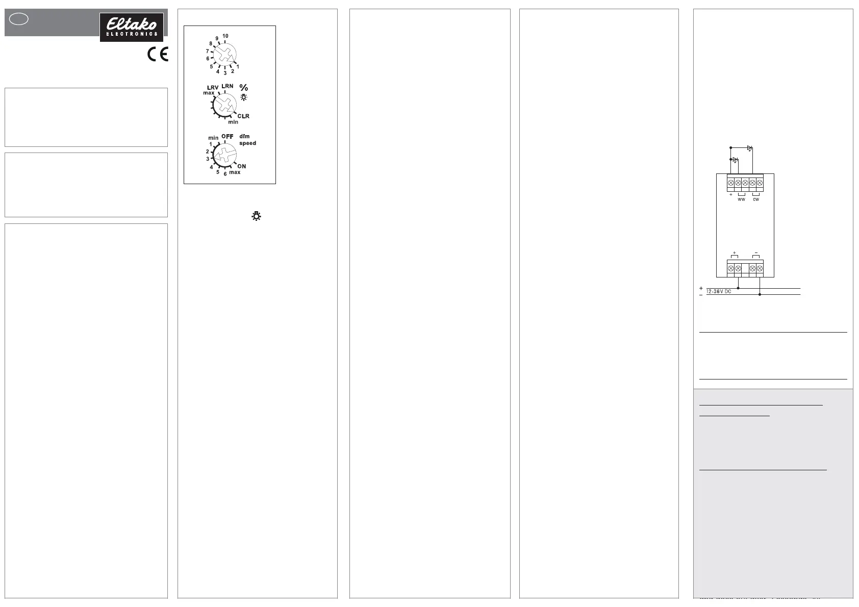
Function rotary switches
The upper rotary switch is only required
for teach-in.
Use the middle % rotary switch to set
the minimum brightness (fully dimmed).
Use the lower dimming speed rotary
switch to set the dimming speed.
The pushbuttons can either be taught in
as direction pushbuttons or universal
pushbuttons: as direction pushbutton,
one side is 'switch on and dim up'; the
other side is 'switch off and dim down'.
Double-click on the switch-on side to
trigger automatic dim up to full bright-
ness at dimming speed. Double-click on
the switch-off side to trigger the snooze
function. As universal pushbutton,
change the direction by briefly releasing
the pushbutton.
FHB wireless motion/brightness sensors
can be taught in as master or slave.
FAH wireless brightness sensors can be
taught in for switch-off dependent on
brightness or as a twilight switch.
Pushbutton 'central off' for 1 channel:
switches off.
Pushbutton 'Central ON' for channel 1:
switches on with the memory value.
Pushbutton 'central off' for all 2 channels:
saves the current lighting scene and
switches off.
Pushbutton 'central ON' for all 2 channels:
switches on with the light scene where
central was switched off most recently.
After a power failure, the memory values
are switched on.
Rotary switch: Press the middle of the
y
rent dimming value. Turn to the right
(clockwise) to dim up. The turning speed
determines the dim-up speed. If the dim-
ming actuator was turned to the right
when it was switched off, the dimmer
will switch on at minimum brightness
and then continue to dim up. If the rotary
knob is turned jerkily – and the actuator
was previously switched on or off – dim-
up is rapid to full brightness. Turn to the
left (anticlockwise) to dim-down to the
minimum brightness which is adjusted
on the dimming actuator. The turning
speed determines the dim-down speed.
If the rotary knob is turned to the left jer-
kily, dim-down is rapid to the minimum
brightness which is adjusted on the dim-
ming actuator.
Intensity rotary switch: (must be
taught-in in both channels) To switch
on, press or turn. To dim up turn right,
to dim down turn left. To switch off press.
White tone rotary switch: (must be
taught-in in both channels) Turn right or
left switches on and change the white
tone, to right warmer and to the left col-
der. Press to switch off and press again
to switch on.
White tone and intensity double rocker
pushbutton:
(must be taught-in in both
channels) rocker upper right switches
on and dim up, rocker bottom right swit-
ches off and dim down. Left rocker up
and down changes the white tone.
Switching for light alarm clocks:
An appropriately taught-in timer wireless
signal starts the wake-up function by
switching on the lighting at lowest
brightness and slowly dimming up to
maximum brightness over a period of
30 minutes (or light scene 5). The dim-
ming process is stopped by tapping
briefly, e.g. on the hand-held transmitter.
Snooze function (universal switch or
direction switch on the switch-off side):
With a double impulse the lighting is
dimmed down from the current dimming
position to the minimum brightness
level and switched off. The current dim-
ming position as well as the adjustable
e
minimum brightness level determine the
dimming time (max. = 30 minutes)
which can be reduced as required. It
can be switched off at any time by
short-time control commands during the
lighting is dimmed down.
Light scenes on the PC are set and
retrieved using the Wireless Visualisation
and Control Software GFVS. One or
several FWWKW71L devices must be
taught in on the PC as dimming switches
with percentage brightness values or
high-definition brightness values.
FBH as Master: When an FBH wireless
motion detector and brightness sensor
is taught in, the switching threshold at
which the lighting is switched on at the
brightness values of light scene 6 is
defined during teach-in using the lower
rotary switch. The switching threshold is
dependent on the brightness in addition
to motion (from approx. 30 lux in position
OFF to approx. 300 lux in max position.
When the FBH in taught-in in the ON
position, it is only evaluated as a motion
detector.
A time delay of 1 minute is a fixed setting
in the FBH.
By switching-off or dimming with push-
button, the FBH is deactivated.
Central pushbutton, scene pusbhbutton
and 'dimming value' by PC also lead to
deactivation. A short press on the switch-
on side of the direction pushbutton, the
FBH is reactivated.
FBH as Slave: The FBH is only evaluated
as motion detector.
FAH as Master: When a wireless
bright-
ness sensor FAH is taught-in, the swit-
ching
threshold is defined by the lower
rotary switch during teach-in. The swit-
ching threshold switches the lighting off
depending on the brightness. Switch-on
is only possible by pressing the pushbutton.
FAH as twilight switch: When an FAH
wire less brightness sensor is taught in,
the switching threshold at which the
lighting is switched on at the brightness
values of light scene 6 is defined during
teach-in using the lower rotary switch.
The switching threshold is dependent on
the brightness (from approx. 0 lux in
Technical data
Standby loss
12 V DC 0.3W
24V DC 0.4W
36V DC 0.5W
Teaching-in wireless sensors in
wire less actuators
All sensors must be taught-in in the
actuators so that they can detect and
execute commands.
Teaching-in actuator FWWKW71L
The teach-in memory is empty on delivery
from the factory. If you are unsure whether
the teach-in memory contains something
or not, you must first clear the memory
contents completely:
Set the middle rotary switch to CLR. The
LED flashes at a high rate. Within the
next 10 seconds, turn the upper rotary
switch three times to the right stop (turn
clockwise) and then turn back away
from the stop. The LED stops flashing
rotary knob to switch on with the memory
value and to switch off and save the cur-
The red LED accompanies the teach-in
process and indicates control commands
in operation by flashing briefly.
The green LED flashes briefly when a
confirmation telegram is sent.
.
position OFF to approx. 50 lux in max
position.
Switch-off takes place at a brightness of
> 200 lux.
Typical connection
.
and goes out after 2 seconds. All
taught-in sensors are cleared.
Clear individual taught-in sensors in the
same way as in the teach-in procedure,
except that you set the middle rotary
switch to CLR instead of LRN, and
operate the sensor. The LED previously
flashing at a high rate goes out.
Clear device configuration:
Set the middle rotary switch to CLR. The
red LED flashes at a high rate. Within the
next 10 seconds, turn the upper rotary
switch six times to the left stop (turn anti-
clockwise) and away again. The red LED
goes out. The factory settings are restored.
Teaching-in sensors:
A total of 116 memory locations are
available.
1. Set the top rotary switch to the
required teach-in function.
1 = timer as wake-up light;
Teach-in FAH or FBH as Master
2 = 'central off';
Teach-in second FBH as slave
3 = universal switch;
Teach-in third FBH as slave;
4 = 'central on';
Teach-in fourth FBH as slave
5 = Teach in direction pushbutton;
Direction pushbutton are automatically
taught-in fully when pressed. Depen-
ding on where the button is pressed,
the functions for switch-on and dim-up
are defined on one side and switch-
off and dim-down on the other side.
6 = teach in sequential light scene
push button, a pushbutton or half of a
double pushbutton is assigned auto-
matically.
7 = Teach in 4-way direct light scene
pushbuttons (a complete pushbutton
with double rocker is assigned auto-
matically). Turn the lower rotary switch
to the following position:
1 = light scene pushbutton for
scenes 1-4
5 = light scene pushbutton for
scenes 5-8
8 = Teach in FAH as twilight switch;
teach-in operating mode push-
button;
teach in intensity rotary wheel
9 = Teach in GFVS and FFD with high
resolution dimming values; teach in
white tone rotary switch wheel
10 = Teach in rotary switch and
GFVS; during teach-in the actuator
automatically sends a confirmation
telegram. Teach in dimming values of
FFD; teach in white tone and intensity
double rocker pushbutton;
Turn the lower rotary switch to the re quired
channel for universal push buttons,
direction pushbuttons and central control
pushbuttons.
min = all 2 channels
1 = channel 1 warm white (ww)
2 = channel 2 cold white (cw)
2. Set the middle rotary switch to LRN.
The LED flashes at a low rate
.
3. Operate the sensor to be taught-in.
The LED goes out.
To prevent unintentional teach-in, turn the
rotary switch back to LRN for every teach-
in process. The LED flashes at a slow rate
.
You can teach in unencrypted and
encrypted sensors.
Teach in encrypted sensors:
1. Set the middle rotary switch to LRV.
The red LED flashes at a high rate.
2. Within 120 seconds, enable sensor
encryption. The red LED goes out.
Caution: Do not switch off the power
supply.
3. Then teach in the encrypted sensor as
described in 'Teaching-in sensors'.
To teach in other encrypted sensors, turn
the middle rotary switch briefly away
from position LRV and then turn it to 1.
With encrypted sensors, use the 'rolling
code', i.e. the code changes in each
telegram, both in the transmitter and in
the receiver.
If a sensor sends more than 50 tele-
grams when the actuator is not enabled,
the sensor is no longer recognised by
the enabled actuator and you must
repeat teach-in as 'encrypted sensor'.
It is not necessary to repeat the function
teach-in.
Saving light scenes
Up to four brightness values retrievable
w
with a direct light scene pushbutton can
be saved.
1. Adjust the required brightness level
with a previously taught-in universal
or direction switch (separate for each
channel if necessary).
2. Within 60 seconds, press one of the
four rocker ends of the previously
taught-in direct light scene pushbutton
for longer than 3 seconds but less
than 10 seconds to save the bright-
ness value.
3. Repeat from point 1 to save further
light scenes.
Retrieving light scenes
Up to 8 light scenes can be retrieved:
Direct light scene pushbutton 1-4 (push-
button with double rocker, top left =
light scene 1, top right = light scene 2,
bottom left = light scene 3 and bottom
right = light scene 4).
Direct light scene pushbutton 5-8 (push-
button with double rocker, top left = light
scene 5, top right = light scene 6, bottom
left = light scene 7 and bottom right =
light scene 8) and/or with a sequential
light scene pushbutton (pushbutton or
half a double pushbutton, press top =
next light scene, press bottom = pre-
vious light scene).
Switch on repeater:
The repeater is switched off in the factory
setting. In deenergised state turn the
middle rotary switch to CLR and the
lower rotary switch to ON. Switch on the
power supply. The red LED lights up to
two seconds. The repeater is switched
on.
Switch off repeater:
In deenergised state turn the middle
rotary switch to CLR and the lower rotary
switch to OFF. Switch on the power supply.
The red LED lights up to 0.5 seconds.
The repeater is switched off.
Switch-on confirmation telegrams:
Set the middle rotary switch to CLR. The
red LED flashes nervously. Now within
10 seconds turn the upper rotary switch
3 times to the left (anticlockwise) and
then back away. The red LED goes out
and the green LED lights up for 2
Switch-off confirmation telegrams:
Set the middle rotary switch to CLR.
The LED flashes nervously. Now within
10 seconds turn the upper rotary switch
3 times to the left (anticlockwise) and
then back away. The red LED goes out
immediately. The confirmation tele-
grams are switched-off.
Master-slave mode:
Activate FWWKW71L as master and
teach in all FWWKW71L slaves simulta-
neously:
1. Switch off the power supply to all
FWWKW71L devices (master and
slaves).
2. On the FWWKW71L master, turn the
upper rotary switch to 1, the middle
rotary switch to LRN and the lower
rotary switch to ON.
3. On all FWWKW71L slaves, turn the
upper rotary switch to 1, the middle
rotary switch to min and the lower
rotary switch to max.
4. Switch on the power supply to all
FWWKW71L devices (master and
slaves) simultaneously. The red LED
lights up for 0.5 seconds and the lamp
of the FWWKW71L master switches to
maximum brightness. After approx.
2 seconds, the green LED on the
FWWKW71L master lights up briefly
and a teach-in telegram is sent. After
the teach-in telegram is received by
FWWKW71L slave, the lamp on the
FWWKW71L slave switches on at
maximum brightness.
5. Set all FWWKW71L devices (master
and slaves) to the same operating
mode, minimum brightness and dim
speed.
Deactivate FWWKW71L as master:
In deenergised state turn the middle
rotary switch to LRN and the lower rotary
switch to OFF. Switch on the power supply
.
The red LED lights up to 0.5 seconds.
The master-telegrams and confirmation
telegrams are switched off.
Teach in direction pushbutton in
FWWKW71L slave (only if required):
Turn the upper rotary switch to 5 and
the bottom rotary switch to the required
channel.
Set the middle rotary switch to LRN. The
LED flashes at a low rate
Press the push button. The LED goes out.
When pressed, a rocker is completely
taught-in automatically. Where you
press first is then defined as switch-on.
The other side automatically becomes
switch-off.
Function of slave direction pushbutton:
Quit slave mode as follows:
Press long on the switch-on side to dim
up to the required value.
Press long on the switch-off side to dim
down to the required value.
Double-click on the switch-on side to
dim automatically to maximum bright-
ness.
Press briefly on the switch-off side to
switch off.
Press briefly on the switch-on side to
change back to slave mode.
If the FWWKW71L master was activated
by a central command, the FWWKW71L
slave changes immediately to slave
mode.
Special modes:
The PCT14 can be used to change the
dimmer operating mode.
When special mode is activated (e.g.
light scene switch-through), the dimmer
is only switched on with Central ON,
Central OFF, FBH or FAH.
Operating modes:
'Rotary switch' (factory setting)
'Simple light scene switch-through':
Light scenes are activated (dimmed)
in the set sequence and time period.
8 light scenes can be defined here.
Various effects can be generated
using the dimming speed and time
setting.
LS1-LS2-LS3-LS4-LS5-LS6-LS7-LS8-
LS1
'Light scene switch-through with
switch-off': Light scenes and OFF are
activated (dimmed) alternately in the
set time period.
seconds. The confirmation telegrams are
switched-on.
Must be kept for later use!
Eltako GmbH
D-70736 Fellbach
Technical Support English:
Michael Thünte +49 176 13582514
thuente@eltako.de
Marc Peter +49 173 3180368
marc.peter@eltako.de
eltako.com
03/2018 Subject to change without notice.
EnOcean wireless
Frequency 868.3MHz
Transmit power max. 10 mW
Hereby, Eltako GmbH declares that the
radio equipment type FWWKW71L is in
compliance with Directive 2014/53/EU.
The full text of the EU declaration of
conformity is available at the fol-
lowing internet address: eltako.com
Cablexation
The cable must be fastened with stan-
dard cable ties (width < 3,6 mm).
.
LS1-AUS-LS2-AUS-LS3-AUS-LS4-AUS-
LS5-AUS-LS6-AUS-LS7-AUS-LS8-AUS-
LS1
'Light scenes in random sequence':
Light scenes are selected and activa-
ted in random sequence in the set
time period.
'Random light scenes': Random events
are triggered in the set sequence. An
event may be a dim-up or dim-down
operation or a light scene.
function of the operating mode push-
button:
Press up: normal mode ('rotary
switch')
Press down: special operating mode
active
Use the data transformer DAT71 to
create a link to a PC running the PCT14
software.
Configure FWWKW71L:
The following points can be configured
using the PC PCT14 tool:
Teach in pushbuttons with single or
double click.
Behaviour after power failure
Minimum brightness
Brightness for light scenes
Preselect colour of light scenes
Operating mode
Time for special operating mode
Master-slave mode
Send dimming value in %: ON or OFF
Send pushbutton telegram ON (0x70)
and OFF (0x50): OFF or ON
Confirmation telegrams
Confirmation flickering when scenes
are saved
PWM frequency (250Hz, 500 Hz,
1kHz, 2kHz, 4kHz)
Dimming speeds
Dim-down delay for motion detector
Light alarm time period
Snooze function time period
Add or change sensors
When an actuator is ready for
teach-in (the LED flashes at a
low rate), the very next incoming
signal is taught-in. Therefore,
make absolutely sure that you
do not activate any other sensors
during the teach-in phase.
!


Product specificaties

Merk: Eltako
Categorie: Niet gecategoriseerd
Model: FWWKW71L

Heb je hulp nodig?

Als je hulp nodig hebt met Eltako FWWKW71L stel dan hieronder een vraag en andere gebruikers zullen je antwoorden


Handleiding Niet gecategoriseerd Eltako

Handleiding Niet gecategoriseerd

Nieuwste handleidingen voor Niet gecategoriseerd