Eltako FT4F-wg Handleiding
Eltako Niet gecategoriseerd FT4F-wg
Bekijk gratis de handleiding van Eltako FT4F-wg (1 pagina’s), behorend tot de categorie Niet gecategoriseerd. Deze gids werd als nuttig beoordeeld door 48 mensen en kreeg gemiddeld 4.3 sterren uit 8 reviews. Heb je een vraag over Eltako FT4F-wg of wil je andere gebruikers van dit product iets vragen? Stel een vraag
Pagina 1/1
FT4F-:
Wireless at pushbuttons, 80x80 mm external
dimensions, internal frame dimensions
63x63 mm, 15 mm high. Generates the power
for wireless telegrams itself when the button
is pressed, therefore there is no connecting
wire and no standby loss.
The scope of supply comprises the frame
R1F, a at rocker WF, a at double rocker
DWF (all same colour), an attachment frame
BRF, the mounting base HP, the wireless
module and one adhesive foil.
FT55-:
Wireless pushbuttons, 80x80 mm external
dimensions, internal frame dimensions
55x55 mm, 15 mm high.
Generates the power for wireless telegrams
itself when the button is pressed, therefore
there is no connecting wire and no standby
loss.
The scope of supply comprises the frame R,
a rocker W55, a double rocker DW55 (all
same colour), an attachment frame BRF, the
mounting base HP, the wireless module and
one adhesive foil.
Wireless pushbuttons with one rocker can
transmit two evaluable signals: press rocker
up and press rocker down. Wireless push-
buttons with double rocker can transmit
four evaluable signals: press two rockers up
or down.
The mounting base can be screwed onto a
at surface or glued to the wall, on glass or
on furniture using the enclosed adhesive
foil. Use the sleeves in the 55 mm socket
box for screw mounting.
Wireless sensor
Wireless at pushbuttons
FT4F-
Wireless pushbuttons FT55-
GB
Temperature at mounting location:
-20°C up to +50°C.
Storage temperature: -25°C up to +70°C.
Relative humidity:
annual average value <75%.
30 000 595 - 1
The double rocker is snapped onto the
wire-
less module at the factory. If the double rocker
is replaced by the large rocker, remove the
rocker halves by pulling off to the front. Do
not bend towards the middle. Then snap the
large rocker so that the markings 0 and I on
the back line up with the same markings on
the wireless module.
Adhesion: First adhere the set
comprising
the mounting base, frame and attachment
frame
- with the latches pointing at the top
and bottom. Then snap on the set
comprising
the wireless module and rocker
- with the
marking 0 on the back always pointing up.
Before screwing, remove the mounting
base from the frame and the attachment
frame. To do this, press the latches on the
mounting base outwards. Then screw the
mounting base - with the latches at top and
bottom -, snap on the frame with the attach-
ment frame and snap on the set
comprising
the wireless module and rocker
- with the
marking 0 on the back always pointing to
the top.
For screw mounting, we recommend stain-
less steel countersunk screws 2.9x25 mm,
DIN 7982 C, for screw connections. Both
with rawl plugs 5x25 mm and with 55 mm
switch boxes.
The Eltako frame can be replaced on
installation at any time by a design frame
with the same internal dimensions from
other manufacturers. FT4F: 63x63 mm,
FT55: 55x55 mm.
The wireless module integrated in the
wireless pushbuttons can be taught-in
encrypted in all encryptable actuators of
the 61 Series, 62 Series and Series 71 as
well as the FAM14. This requires the FTVW
wireless pushbutton encryption rocker.
Encryptable actuators bear the pictogram
.
Pushbuttons with engraving +0I:
If wireless pushbuttons are taught-in as
direction switches in a building, it is then
recommended to t any central control switch
with the engraving 0/I rotated through 180°.
Then the central switch-on (I) is at the top
as well as the switch-on for the direction
switches.
Teaching-in wireless sensors in wire-
less actuators
All sensors must be taught-in in the
actuators so that they can detect and
execute commands.
The teach-in process is described in the
operating instructions of actuators.
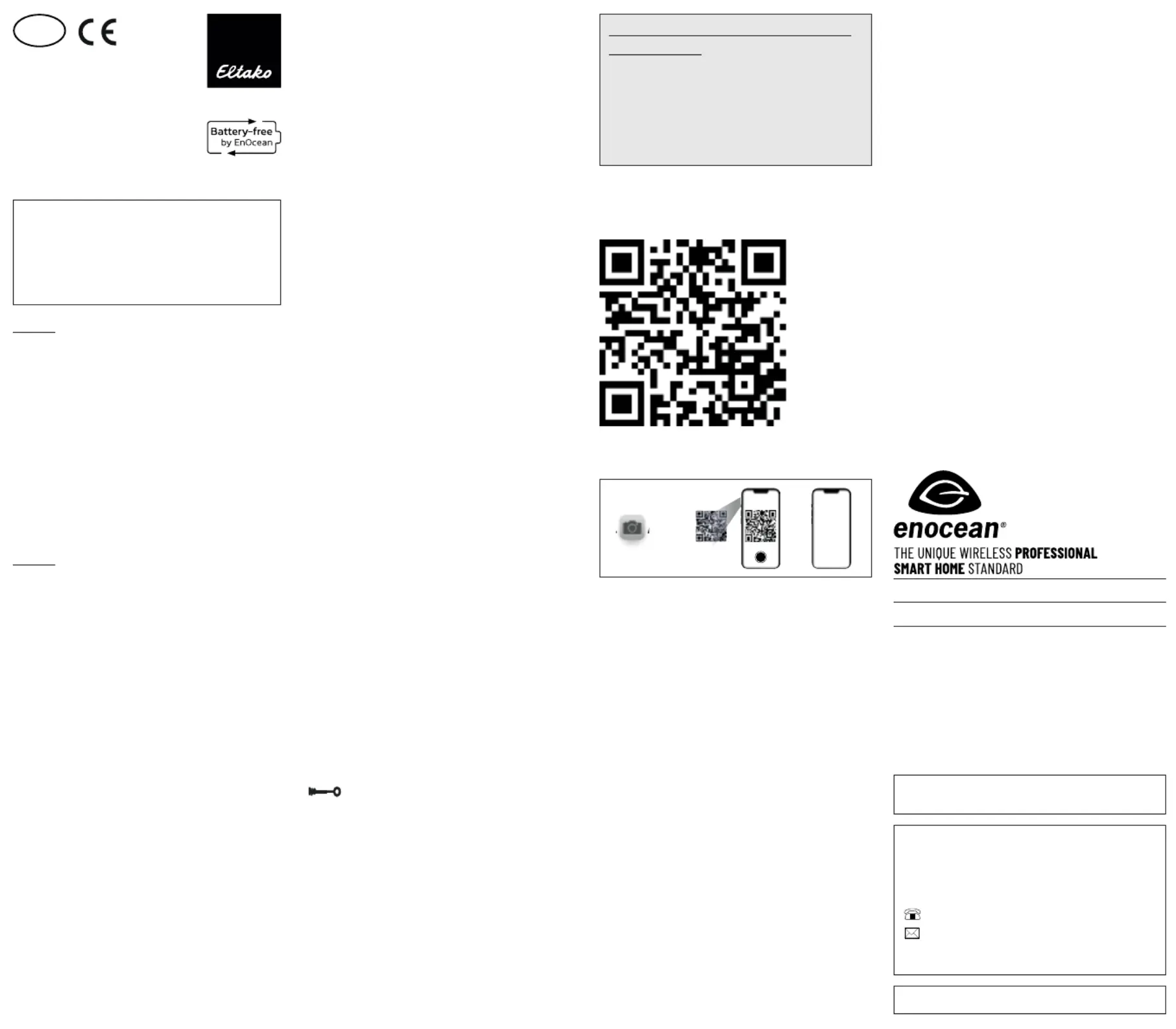
Manuals and documents in further
languages
http://eltako.com/redirect/FT4F-_FT55-
1.App 2. 3.
www.
Frequency 868.3 MHz
Transmit power max. 10 mW
Hereby, Eltako GmbH declares that the radio
equipment type FT4F-, FT55- is in com-
pliance with Directive 2014/53/EU.
The full text of the EU declaration of
conformity is available at the following
internet address: eltako.com
Must be kept for later use!
Eltako GmbH
D-70736 Fellbach
Technical Support English:
+49 711 943 500 25
technical-support@eltako.de
eltako.com
42/2022 Subject to change without notice.
Product specificaties
| Merk: | Eltako |
| Categorie: | Niet gecategoriseerd |
| Model: | FT4F-wg |
Heb je hulp nodig?
Als je hulp nodig hebt met Eltako FT4F-wg stel dan hieronder een vraag en andere gebruikers zullen je antwoorden
Handleiding Niet gecategoriseerd Eltako

21 Juli 2026
20 Juli 2026
14 April 2025
14 April 2025
13 Maart 2024
21 Februari 2024
21 Februari 2024
21 Februari 2024
21 Februari 2024
20 Februari 2024
Handleiding Niet gecategoriseerd
Nieuwste handleidingen voor Niet gecategoriseerd
21 Juli 2026
21 Juli 2026
21 Juli 2026
21 Juli 2026
21 Juli 2026
21 Juli 2026
21 Juli 2026
21 Juli 2026
21 Juli 2026
21 Juli 2026