Eltako FTN14 Handleiding
Eltako Niet gecategoriseerd FTN14
Bekijk gratis de handleiding van Eltako FTN14 (2 pagina’s), behorend tot de categorie Niet gecategoriseerd. Deze gids werd als nuttig beoordeeld door 98 mensen en kreeg gemiddeld 4.2 sterren uit 8 reviews. Heb je een vraag over Eltako FTN14 of wil je andere gebruikers van dit product iets vragen? Stel een vraag
Pagina 1/2
Staircase off-delay timer,1NO contact not
potential free16A/250V AC, incandescent
lamps up to 2000 watts, switch-off early
warning and switchable pushbutton
permanent light. Also for energy saving
lamps ESL up to 200 Watt. Bidirectional.
Only 0.2 watt standby loss.
Modular device for DIN-EN 60715 TH35
rail mounting.
1module =18mm wide, 58mm deep.
Connection to the Eltako-RS485 bus.
Bus cross wiring and power supply with
jumper.
Switching voltage 230V.
Zero passage switching to protect
contacts and consumers.
When the power supply fails, the switching
state will be maintained. With recurring
supply voltage, the timing starts at the
end of which it will be switched off.
In addition to the bus control input, this
staircase off-delay timer can also be
controlled locally by a conventional
230V control switch. Glow lamp current
up to 5mA, dependent on the ignition
voltage of the glow lamps.
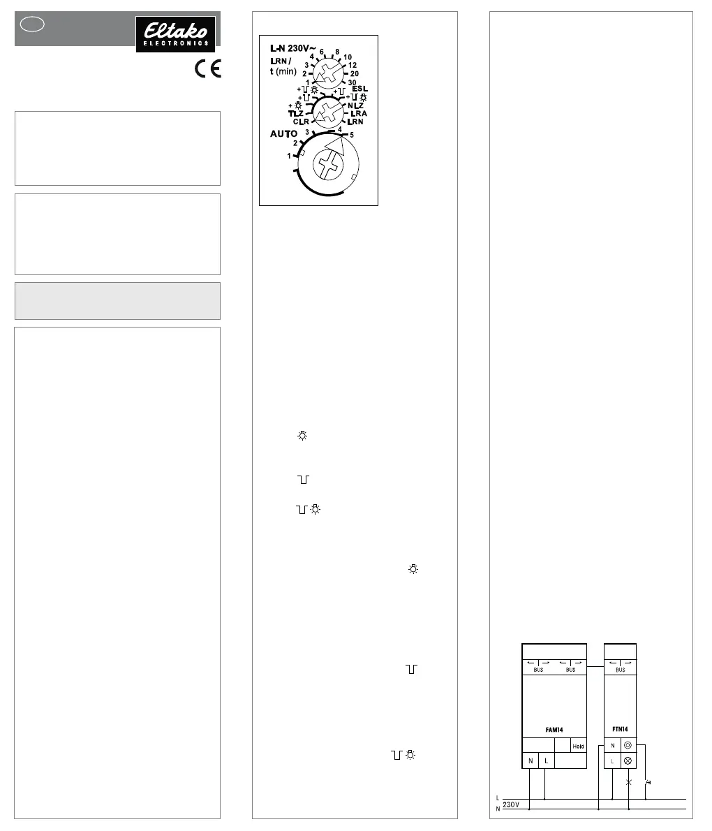
Function rotary switches
GB
Only skilled electricians may install
this electrical equipment otherwise
there is the risk of fire or electric
shock!
Temperature at mounting location:
-20°C up to +50°C.
Storage temperature: -25°C up to +70°C.
Relative humidity:
annual average value <75%.
RS485 bus actuator
Staircase off-delay timer
FTN14
30014 011-2
valid for devices from production week
40/17 (see bottom side of housing)
Function rotary switches
The upper rotary switch LRN is required
for teach-in. Then the off-delay1to
30 minutes can be set.
Wireless pushbuttons and/or wireless
motion-brightness sensors FBH will be
taught-in with the middle rotary switch
in the setting LRN, of which one or more
are central control push buttons. The re-
quired function of this staircase off-delay
timer can then be selected:
NLZ= off-delay timer with adjustable
operate delay
TLZ= staircase time switch
ESL= staircase time switch for energy
saving lamps ESL
+= with pushbutton
permanent light
(only TLZ)
+= with switch-off early
warning (TLZ + ESL)
+= with pushbutton
permanent light and
switch-off early warning
(TLZ + ESL)
If the permanent light functionis
switched on, the function can be activated
by pressing the pushbutton for longer
than1second. This function switches off
automatically after 60 minutes or by
pressing the pushbutton for longer than
2 seconds.
If the switch-off early warningis
switched on, the light starts to flicker
approx. 30 seconds before time-out.
This is repeated three times at decreasing
time intervals.
If both switch-off early warning and
push button permanent light are
switched on, switch-off early warning is
activated before automatic switch-off of
the permanent light.
A res
p
onse dela
y
(
AV dela
y)
can be set
Setting AUTO1=1s, AUTO2 = 30s, AU-
TO3 = 60s, AUTO4 = 90s and AUTO5
=120s (clockwise). Also permanent
light function can be set manually.
If in contrast NLZ will be controlled with
a pushbutton, then it will be switched on
with the1st key and the timing starts at
the 2nd key at the end of which it will be
switched off.
When teaching-in wireless motion/
brightness sensors FBH (Master),the
switching threshold is defined on the
last FBH taught-in to switch the light
on/off depending on the brightness -
provided motion is detected. Possibly
becomes an already taught-in FBH
(Master) automatically removed.
However several FBH (slave) can be
taught-in. The off delay set on the FTN14
is prolonged by a setting of1minute
fixed in the FBH.
At FB65B, the light will turn on after a
motion detection. 2 minutes after the
last detected motion, the light will turn off,
an eventual RV time is added to these
2 minutes.
When teaching-in window/door contacts
FTK and (or) window handles,a NC or
NO can be taught-in as required.
Accordingly, the timing period starts when
opening or closing the window or the door.
If switches for permanent operationare
taught-in, for example wireless transmitter
modules or FTS14EM, it is switched on
when pressing and the time will be started
when releasing.
The LED performs during the teach-in
process according to the operation
manual. It shows control commands by
short flickering during operation.
Typical connection
the
permanent
light.
A response delay (AV delay) can be set
with the lower rotary switchat setting
NLZor when controlled with a switch.
Product specificaties
| Merk: | Eltako |
| Categorie: | Niet gecategoriseerd |
| Model: | FTN14 |
Heb je hulp nodig?
Als je hulp nodig hebt met Eltako FTN14 stel dan hieronder een vraag en andere gebruikers zullen je antwoorden
Handleiding Niet gecategoriseerd Eltako

14 April 2025
14 April 2025
13 Maart 2024
21 Februari 2024
21 Februari 2024
21 Februari 2024
21 Februari 2024
20 Februari 2024
20 Februari 2024
20 Februari 2024
Handleiding Niet gecategoriseerd
Nieuwste handleidingen voor Niet gecategoriseerd
9 Maart 2026
9 Maart 2026
9 Maart 2026
9 Maart 2026
9 Maart 2026
9 Maart 2026
9 Maart 2026
9 Maart 2026
9 Maart 2026
9 Maart 2026