Eltako FUD71L Handleiding


Lees hieronder de 📖 handleiding in het Nederlandse voor Eltako FUD71L (4 pagina's) in de categorie Niet gecategoriseerd. Deze handleiding was nuttig voor 11 personen en werd door 2 gebruikers gemiddeld met 4.5 sterren beoordeeld

Pagina 1/4
Wireless actuator
Universal dimmer switch
FUD71L/1200 W-230 V
30 100 846 - 3
Universal dimmer switch, power MOSFET up
to 1200 W. Automatic lamp detection. With
adjustable minimum brightness and dimming
speed. With switching operation for light
alarm clocks, children's rooms and snooze
function as well as constant light regulation
and master-slave mode. Also with light scene
control by PC or wireless pushbuttons. Enc-
rypted wireless, bidirectional wireless and
repeater function are switchable. Only 0.7
watt standby loss.
Mounting in the 230 V power supply cord, e.g.
in false ceilings and lamps. 252 mm long,
46 mm wide und 31 mm high.
Universal dimmer switch for lamps up to
1200 W, depending on ventilation conditions.
Dimmable energy saving lamps ESL and
dimmable 230 V LED lamps, additionally de-
pending on the lamps electronics.
Zero passage switching with soft ON and
soft OFF to protect lamps.
The brightness level is stored on switch-off
(memory).
In case of a power failure the switch position
and the brightness stage are stored and may be
switched on when the power supply is restored.
Automatic electronic overload protection
and overtemperature switch-off.
Encrypted sensors can be taught in.
You can switch on bidirectional wireless
and/or a repeater function.
GB
Temperature at mounting location:
-20°C up to +50°C.
Storage temperature: -25°C up to +70°C.
Relative humidity:
annual average value <75%.
Only skilled electricians may install this
electrical equipment otherwise there is
the risk of re or electric shock!
valid for devices from production week
50/16 (see bottom side of housing)
Every change in state and incoming central
command telegrams are conrmed by a wi-
reless telegram. This wireless tele gram can
be taught-in in other actuators, in universal
displays FUA55 and in the GFVS software.
The current dimming value is also displayed
in % in the GFVS-Software.
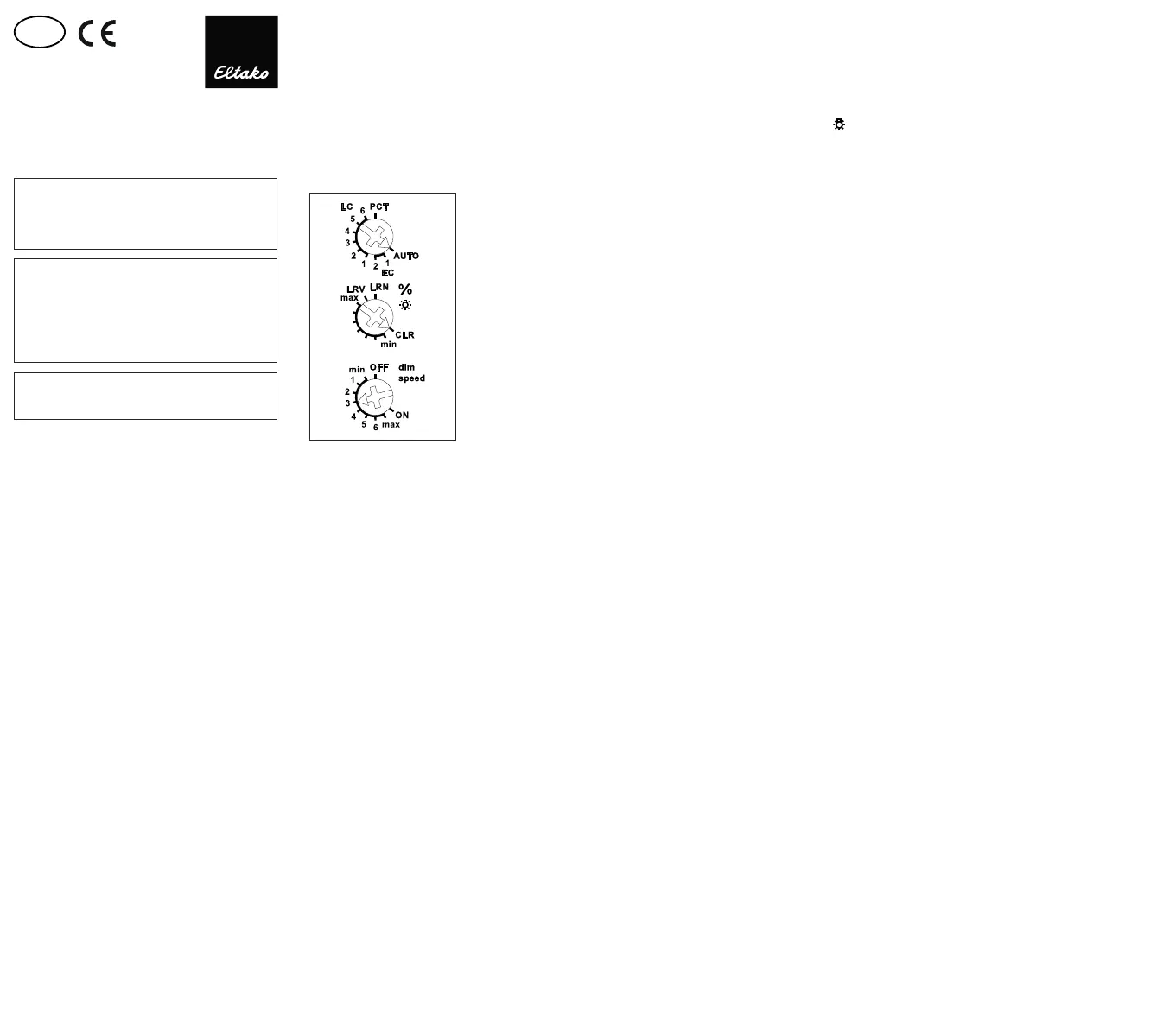
Function rotary switches
The upper rotary switch determines the
operation, whether automatic lamp detection
or special comfort positions should work:
AUTO allows the dimming of all lamp types.
EC1 is a comfort position for energy saving
lamps, which which by design must be tur-
ned on with an increased voltage so that
they switch on again in cold state when
dimmed down.
EC2 is a comfort position for energy saving
lamps, which by design won't switch on
again when dimmed down. Therefore Me-
mory is switched off in this position.
LC1 is a comfort position for dimmable 230 V
LED lamps, which by design won't be dimmed
down enough in the AUTO position (trailing
phase angle) and therefore has to be forced
to leading phase angle.
LC2 and LC3 are comfort positions for dim-
mable 230 V LED lamps like LC1 but with dif-
ferent dimming curves.
In positions EC1, EC2, LC1, LC2 and LC3 in-
ductive (wound) transformers may not be
used. In addition, the maximum number of
dimmable LED lamps may be lower by design
than in the AUTO position.
LC4, LC5 and are comfort positions for LC6
LED lamps like AUTO but with different dim-
ming curves.
PCT is a position for special functions which
were set up using the PCT14 PC Tool. The
PCT14 link is hooked up using the data
transformer DAT71.
The minimum brightness (fully dimmed
down) is adjustable with the middle %
rotary switch.
The dimming speed is adjustable using the
lower dimming speed rotary switch.
The pushbuttons can be either taught-in
as direction pushbuttons or universal
pushbuttons: As direction pushbutton
'switch on and dim up' is on one side and
'switch off and dim down' on the other side.
A double-click on the switch on side triggers
the automatic dimming up to full brightness
with dim speed time. A double-click on the
switch off side triggers the snooze function.
The children's room function is triggered on
the switch on side. As a universal push-
button the direction change is made by
briey releasing the push button.
Switching for light alarm clocks: An ap-
propriately taught-in timer wireless signal
starts the wake-up function by switching on
the lighting at lowest brightness and slowly
dimming up to maximum brightness over a
period of 30 minutes. The dimming process
is stopped by tapping briey, e.g. on the
hand-held transmitter. In the settings EC no
switching for light alarm clocks is possible.
Switching operation for children's rooms
(universal switch or direction switch on the
switch-on side): If the light is switched on
by holding down the pushbutton, it starts at
the lowest brightness level after approx. 1
second and dims up slowly as long as the
pushbutton is held down without modifying
the last stored brightness level.
Snooze function (universal switch or
direction switch on the switch-off side):
With a double impulse the lighting is dim-
med down from the current dimming positi-
on to the minimum brightness level and
switched off. The current dimming position
as well as the adjustable minimum brightness
level determine the dimming time (max. = 60
minutes) which can be reduced as required.
It can be switched off at any time by short-
time control commands during the lighting is
dimmed down.
Light scenes on the PC are set and
retrieved using the Wireless Visualisation
and Control Software GFVS. One or several
FUD71 devices must be taught in on the PC
as dimming switches with percentage
brightness values.
A resettable staircase time switch function
with RV = 2 minutes can be called by a push-
button taught-in as a staircase pushbutton.
Brightness level settings can be called during
teach-in with single light scene pushbuttons.
A twilight pushbutton can be implemented
using a taught-in FAH. Switch-on can be
performed dependent on motion and bright-
ness with up to 4 FBH devices.
Wireless pushbutton Central ON:
The impulse length is not important. The push-
button switches on with the memory value.
Wireless pushbutton Central OFF:
The impulse length is not important. The
pushbutton switches off.
Staircase light pushbutton:
The staircase light pushbutton switches on
with a memory value and starts an RV time
of 2 minutes at the end of which the device
switches off. Press the pushbutton again to
restart.
FTK as NO contact:
When the window is opened, the light is
switched on. When the window is closed,
the light is switched off.
FTK as NC contact:
When the window is opened, the light is
switched off. When the window is closed,
the light is switched on.
Either a FBH or a FHD60 can be taught-in
as master:
FBH as Master: (automatic brightness con-
trol) When a wireless motion/brightness
sensor FBH is taught-in, the switching
threshold is dened by the lower rotary
switch during teach-in.
The switching threshold switches on the
lighting with memory value depending on
the brightness (in addition to motion) (from
approx. 30 Lux in OFF position to approx.
300 Lux in ON position). When the FBH in
taught-in in the ON position, it is only evalu-
ated as a motion detector.
A return delay of 2 minutes is preset in the
FUD71.
By switching-off or dimming with pushbut-
ton, the FBH is deactivated. Central push-
button, scene pusbhbutton and 'dimming
value' by PC also lead to deactivation. A
short press on the switch-on side of the di-
rection pushbutton, the FBH is reactivated.
FBH as Slave: The FBH is only evaluated as
motion detector.
Semi-automatic motion detection with
taught-in FB65B wireless motion sensor
(factory setting): After switching on via
pushbutton, the 5 minutes delay time
starts, within this time the delay will
restart
after each detected motion. 5 minutes
after
the last detected motion it will switch off. If
a motion is detected 5 minutes after swit-
ching off, it will automatically switch on
again. After this time only a pushbutton can
switch on. The pushbutton is allowed to
switch off at any time, then the motions are
no more evaluated.
Fully automatic motion detection with
FB65B taught-in wireless motion sensor:
If the actuator should switch on automatically
when motion is detected, e.g. in rooms
without daylight, replug the jumper to 'active'
on the FB65B device. When motion is no
longer detected, the device switches off
automatically after the 5 minutes release
delay time expires. Press the pushbutton at
any time to switch the device on or off.
When motion is detected, the device switches
on again automatically.
FHD60 as Master: (automatic brightness
control off) When a wireless brightness and
twilight sensor FHD60 is taught-in, the swit-
ching threshold is dened by the lower
rotary button during teach-in. The swit-
ching threshold switches the lighting off
depending on the brightness. Switch-on is
only possible by pressing the push button.
FHD60 as twilight switch: (automatic
brightness control off) When a wireless
brightness and twilight sensor FHD60 is
taught-in, the switching threshold is de-
ned by the lower rotary switch during
teach-in. The switching threshold switches
the lighting on or off depending on the
brightness (from approx. 0 Lux in OFF posi-
tion to approx. 50 Lux in ON position). If the
brightness threshold is under shot, switch-on
uses the memory value. Switch-off takes
place at a brightness of > 200 Lux.
FHD60 as twilight dimmer: (automatic
brightness control off) When a wireless
brightness and twilight sensor FHD60 is
taught-in, the minimum dimming value is
dened in % by the lower rotary switch. The
switching threshold is the value to which
the lighting is dimmed down in darkness
(OFF = minimum dimming value to ON = ma-
ximum dimming value). If the brightness
undershoots a xed limit, switch-on takes
place at maximum dimming value. If the
brightness drops, the dimming value is also
reduced. When the brightness rises again,
the dimming value also increases. If the
brightness exceeds the xed limit, the ligh-
ting is switched off.
Constant light control with FHD65:
(The automatic brightness control automa-
tically switches on when teaching-in of the
FHD65) The required brightness is adjusted
by a pushbutton, then the rst received
brightness value of the FHD65 is the target
brightness, it is maintained constant auto-
matically by the FUD71 by incoming bright-
ness values of the FHD65. After each
change in brightness (dimming) with push-
button, the subsequently received bright-
ness value of FHD65 will be the new target
brightness. If the target brightness is
adjusted with a 'direction pushbutton for
target brightness', this is xed, a change in
brightness with the pushbutton is then
overruled by the xed target brightness. If
additionally a FBH is taught-in as a slave, it
is switched on when motion and target
brightness are fallen short and switched off
when not in motion or target brightness is
exceeded. By switching off with pushbut-
ton, the automatic control by FBH or FHD65
is disabled. Central pushbutton, scene
pushbutton
and 'dimming value' by PC also lead to
deactivation. The automatic control is
reactivead by w short press on the switch-
on side of the direction button.
Storing of target brightness:
Press 'direction pushbutton for target
brightness' above. The current brightness
that has been sent from the FHD65 is
stored.
Deletion of target brightness:
Press 'direction pushbutton for target
brighntess' below.
The red LED accompanies the teach-in
process and indicates control commands in
operation by ashing briey.
The green LED ashes briey when a con-
rmation telegram is sent.
Typical connection
Technical data
Incandescent and up to 1200 W
halogen lamps1)
230 V (R)
Inductive up to 1200 W 2)3)
transformers (L)
Electronic up to 1200 W 2)3))
transformers (C)
Dimmable energy up to 1200 W 5)
saving lamps ESL
Dimmable LEDs up to 1200 W 5)
Max./min. temperature +50°C/-20°C 4)
at mounting location
Standby loss (activ power) 0.7 W
1) For lamps with a maximum of 150 W.
2) Per dimmer it is only allowed to use max. 2 inductive
(wound) transformers of the same type, furthermore
no-load operation on the secondary part is not
permitted. Possibly the dimmer switch will be dest-
royed! No load-switching-off on the secondary part is
allowed. The parallel operation of inductive (wound) and
capacitive (electronic) transformers is not allowed!
3) When calculating the load 20% loss has to be consi-
dered for inductive (wound) transformers and 5%
loss in addition to the lamp load
4) Affects the maximum switching power.
5)
Usually applies for dimmable energy saving lamps and
dimmable 230 V LEDs. Due to differences in the lamps
electronics, there may be limited dimming range, switch
on and off problems dependent on the manufacturer
and a restriction on the maximum number of lamps;
especially if the connected load is very low (for 5W-LEDs).
The comfort positions EC1, EC2, LC1, LC2 and LC3 opti-
mize the dimming range, which, however, only gives a
maximum power up to 300W. No inductive (wound)
transformers may be dimmed in these comfort positions.
Teaching-in wireless sensors in wirel-
ess actuators
All sensors must be taught-in in the ac-
tuators so that they can detect and
execute commands.
Teaching-in actuator
FUD71L/1200 W-230 V
The teach-in memory is empty on delive-
ry from the factory. If you are unsure
whether the teach-in memory contains
something or not, you must rst clear
the memory contents completely: Set
the middle rotary switch to CLR. The LED
ashes at a high rate. Within the next 10
seconds, turn the upper rotary switch
three times to the right stop (turn clock
wise) and then turn back away from the
stop. The LED stops ashing and goes
out after 2 seconds. All taught-in sen-
sors are cleared. Clear individual
taught-in sensors in the same way as in
the teach-in procedure, except that you
set the middle rotary switch to CLR
instead of LRN, and operate the sensor.
The LED previously ashing at a high ra-
te goes out.
Clear device conguration: Set the
middle rotary switch to CLR. The red LED
ashes at a high rate. Within the next 10
seconds, turn the upper rotary switch six
times to the left stop (turn anticlockwise)
and away again. The red LED goes out.
The factory settings are restored.
Teaching-in sensors:
A total of 120 memory locations are
available.
1. Set the top rotary switch to the required
teach-in function:
AUTO = timer as wake-up light;
Teach-in FHD65, FHD60 or FBH as master.
EC1 = 'central off';
Teach-in second FBH, FB65B as slave.
EC2 = universal switch;
Teach-in third FBH, FB65B as slave.
LC1 = 'central on';
Teach-in fourth FBH, FB65B as slave.
LC2 = Teach in direction pushbutton,
direction pushbutton are automatically
taught-in fully when pressed. Depen-
ding on where the button is pressed,
the functions for switch-on and dim-up
are dened on one side and switch-off
and dim-down on the other side. Teach
in FTK and Hoppe window handle as NO
contact;
LC3 = teach in sequential light scene
push button, a pushbutton or half of a
double pushbutton is assigned automa-
tically. Teach in FTK and Hoppe window
handle as NC contact.
LC4 = Teach in 4-way direct light scene
pushbuttons, a complete pushbutton
with double rocker is assigned automa-
tically.
LC5 = Teach-in single light scene push-
buttons. Teach in FHD60 as twilight
switch.
LC6 = Teach in staircase light switch;
Teach in FHD60 as twilight dimmer
PCT = Teach-in rotary switch and GFVS,
this automatically switches on and
sends conrmation telegrams. Teach-
in dimming values of FFD; Teach-in 'di-
rection pushbutton for target brightness.
2. Set the middle rotary switch to LRN.
The LED ashes at a low rate.
3. Operate the sensor to be taught-in. The
LED goes out.
To prevent unintentional teach-in, turn
the rotary switch back to LRN for every
teach-in process. The LED ashes at a
slow rate.
You can teach in unencrypted and enc-
rypted sensors.
Teach in encrypted sensors:
1. Set the middle rotary switch to LRV.
The red LED ashes at a high rate.
2. Within 120 seconds, enable sensor enc-
ryption. The red LED goes out. Caution:
Do not switch off the power supply.
3. Then teach in the encrypted sensor as
described in 'Teaching-in sensors'.
To teach in other encrypted sensors,
turn the middle rotary switch briey
away from position LRV and then turn it
to 1. With encrypted sensors, use the
'rolling code', i.e. the code changes in
each telegram, both in the transmitter
and in the receiver.
If a sensor sends more than 50 tele-
grams when the actuator is not enabled,
the sensor is no longer recognised by the
enabled actuator and you must repeat
teach-in as 'encrypted sensor'. It is not
necessary to repeat the function teach-in.
Saving light scenes
Up to four brightness values retrievable with
a direct light scene pushbutton can be saved.
1. Turn he upper rotary switch to the appro-
priate operating mode AUTO, EC or LC.
2. Adjust the required brightness level with
a previously taught-in universal or direc-
tion switch.
3. Within 60 seconds, press one of the four
rocker ends of the previously taught-in
direct light scene pushbutton for longer
than 3 seconds but less than 10 seconds
to save the brightness value.
4. Repeat from point 2 to save further di-
rectly retrievable light scenes.
Retrieving light scenes
Up to four brightness values are retrievable
using a direct light scene pushbutton (push-
button with double rocker, top left = light
scene 1, top right = light scene 2, bottom left
= light scene 3 and bottom right = light scene
4) and/or using a sequential light scene push-
button (pushbutton or one half of a double
push - button, press top = next light scene,
press bottom = previous light scene).
Switch on repeater: The repeater is swit-
ched off in the factory setting. In deenergi-
sed state turn the middle rotary switch to
CLR and the lower rotary switch to ON.
Switch on the power supply. The red LED
lights up to two seconds. The repeater is
switched on.
Switch off repeater: In deenergised state
turn the middle rotary switch to CLR and the
lower rotary switch to OFF. Switch on the
power supply. The red LED lights up to 0.5
seconds. The repeater is switched off.
Switch-on conrmation telegrams:
For deliveries ex-works the conrmation te-
legrams are switched-off. Set the middle
rotary switch to CLR. The red LED ashes
nervously. Now within 10 seconds turn the
upper rotary switch 3 times to the left (an-
ticlockwise) and then back away. The red
LED goes out and the green LED lights up
for 2 seconds. The conrmation telegrams
are switched-on.
Switch-off conrmation telegrams:
Set the middle rotary switch to CLR. The
LED ashes nervously. Now within 10 se-
conds turn the upper rotary switch 3 times
to the left (anticlockwise) and then back
away. The red LED goes out immediately.
The conrmation telegrams are switched-off.
Master-slave mode:
Activate FUD71 as master and teach in all
FUD71 slaves simultaneously:
1. Switch off the power supply to all FUD71
devices (masters and slaves).
2. On the FUD71 master, turn the upper ro-
tary switch to AUTO, the middle rotary
switch to LRN and the lower rotary
switch to ON.
3. On all FUD71 slaves, turn the upper rotary
switch to AUTO, the middle rotary switch
to min and the lower rotary switch to
max.
4. Switch on the power supply to all FUD71
devices (masters and slaves) simultane-
ously. The red LED lights up for 0.5 se-
conds and the lamp of the FUD71 master
switches to maximum brightness. After
approx. 2 seconds, the green LED on the
FUD71 master lights up briey and a
teach-in telegram is sent After the teach
in lights up briey and a teach in tele-
gram is sent. After the teach-in telegram
is received by FUD71 slave, the lamp on
the FUD71 slave switches on at maximum
brightness.
5. Set all FUD71 devices (masters and sla-
ves) to the same operating mode mini-
mum brightness and dim speed.
Deactivate FUD71 as master:
In deenergised state turn the middle rotary
switch to LRN and the lower rotary switch to
OFF. Switch on the power supply. The red
LED lights up to 0.5 seconds. The Master-te-
legrams and conrmation telegrams are
switched off.
Teach in direction pushbutton in FUD71
slave (only if required):
Turn the upper rotary switch to LC2. Turn
the middle rotary switch to LRN. The LED
ashes at a low rate. Press the push - but-
ton. The LED goes out.
When pressed, a rocker is completely
taught-in automatically. Where you press
rst is then dened as switch-on. The other
side automatically becomes switch-off.
Function of slave direction pushbutton:
Quit slave mode as follows: Press long on
the switch-on side to dim up to the required
value. Press long on the switch-off side to
dim down to the required value. Double-
click on the switch-on side to dim automati-
cally to maximum brightness. Press briey
on the switch-off side to switch off. Press
briey on the switch-on side to change back
to slave mode.
If the FUD71 master was activated by a cen-
tral command, the FUD71 slave changes im-
mediately to slave mode.
Use the data transformer DAT71 to create a
link to a PC running the PCT14 software.
Congure FUD71:
The following points can be congured
using the PC PCT14 tool:
Teach in buttons with single or double
click
Behaviour after power failure
Minimum and maximum brightness
Memory
Dimming speeds
Send dimming value in %: ON or OFF
Send pushbutton telegram ON (0x70)
and OFF (0x50): OFF or ON
Switch-on/off speed
Acknowledgement telegrams
Parameters for the operation with
FHD60, FHD65 and FBH
Parameters for operating as clock
Parameters for operating as staircase
time pushbutton
Add or change sensors
Saving light scenes:
Use the PCT14 PC Tool to congure the fol-
lowing parameters:
Conrmation ash when scenes are saved:
ON or OFF.
Light alarm circuit:
Use the PCT14 PC Tool to congure the fol-
lowing parameters: Maximum brightness:
50 to 100%.
Runtime: 1 to 255 minutes (factory setting
30 minutes).
Children's room circuit:
Use the PCT14 PC Tool to congure the fol-
lowing parameters: Save memory value:
OFF or ON.
Dimming speed: 0 (slow) to 255 (fast).


Product specificaties

Merk: Eltako
Categorie: Niet gecategoriseerd
Model: FUD71L

Heb je hulp nodig?

Als je hulp nodig hebt met Eltako FUD71L stel dan hieronder een vraag en andere gebruikers zullen je antwoorden


Handleiding Niet gecategoriseerd Eltako

Handleiding Niet gecategoriseerd

Nieuwste handleidingen voor Niet gecategoriseerd