Eltako FTS14EM T Handleiding
Eltako Niet gecategoriseerd FTS14EM T
Bekijk gratis de handleiding van Eltako FTS14EM T (2 pagina’s), behorend tot de categorie Niet gecategoriseerd. Deze gids werd als nuttig beoordeeld door 216 mensen en kreeg gemiddeld 4.9 sterren uit 4 reviews. Heb je een vraag over Eltako FTS14EM T of wil je andere gebruikers van dit product iets vragen? Stel een vraag
Pagina 1/2
Input module
FTS14EM
Input module for the Eltako RS485 bus,
10 control inputs for universal control
voltage. Only 0.1 watt standby loss.
Modular device for DIN-EN 60715 TH35
railmounting. 2 modules = 36 mm wide,
58 mm deep.
Connection to the Eltako-RS485 bus. Bus
cross wiring and power supply with jumper.
Operation in conjunction with FTS14KS or
FAM14.
A 12 V DC voltage is supplied from a switching
power supply unit FSNT14-12V/12W which
has a width of only 1 module.
10 control inputs +E1 to +E10/-E electrically
isolated from the supply voltage. Control
voltage: 8..230 V UC.
The control inputs can be either activated
for pushbuttons (delivery state), window-
door contacts or motion detectors.
From the production week 21/19 the signals
of the control inputs can be inverted.
Control inputs for pushbuttons:
telegrams of pushbuttons will be generated
(e.g. 0x70). Each FTS14EM can be set to UT
(= universal pushbutton) or RT (= direction
pushbutton) on the lower rotary switch.
Control inputs for window-door contacts:
telegrams of the window-door contact FTK
are generated (EEP D5-00-01). If the input is
driven by the contact with the control voltage
GB
Temperature at mounting location:
-20°C up to +50°C.
Storage temperature: -25°C up to +70°C.
Relative humidity:
annual average value <75%.
30 014 060 - 3
Only skilled electricians may install this
electrical equipment otherwise there is
the risk of re or electric shock!
valid for devices from production week
11/21 (see bottom side of housing)
to be applied externally, the telegram 'window
open' is generated. If the windows-door
contact is opened, the telegram 'window
open' is generated. As with the wireless
sensor FTK, the status telegram is repeated
every 15 minutes.
Control inputs for motion detectors:
telegrams of the wireless motion/brightness
sensor FBH are generated (EEP A5-08-01),
wherein the brightness value is always 0. If
the input is driven by the motion-detectors-
contact with the control voltage to be
applied externally, the telegram 'motion' is
generated. If the contact is opened, the
telegra 'no motion' will be generated. As
with the wireless sensors FBH, the status
telegram is repeated every 15 minutes.
Each telegram of a contact input has to be
taught-in with an identi cation number (ID)
into one or more actuators according to the
operating instructions.
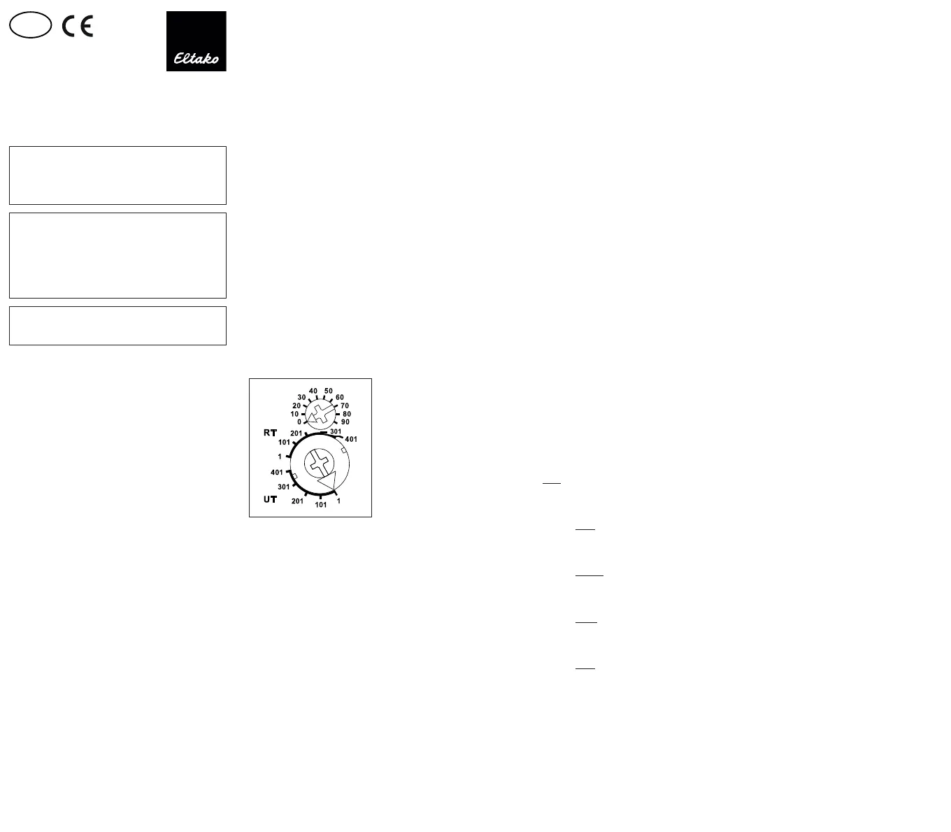
Function rotary switches
The lower rotary switch denes the group
to which an FTS14EM belongs. A total of 5
groups are available (1, 101, 201, 301 and 401)
each with 100 IDs. The upper rotary switch
(0 to 90) sets the ID within a group. The ID
range within a group results from the com-
bination of upper and lower rotary switches
and must be set differently on each FTS14EM.
Maximum ten FTS14EMs form a group. There-
fore, a total of 50 FTS14EMs comprising 500
pushbuttons or contacts are possible in one
RS485 bus.
To generate the necessary teach-in telegrams
for teaching-in into the actuators, the re-
quested group has to be selected on the
upper and lower rotary switch. For push-
buttons in the range UT or RT or for window-
door contacts and motion sensors in the
range RT. Then con rm the required control
input.
In operation, the same group must be selected
in the range UT or RT for push buttons or UT
for window/door contacts and motion sensors.
The LED below the upper rotary switch ashes
brie y, when a connected contact is closed.
Optional: An FAM14 wireless antenna module
(from Wireless Building System) which is only
two modules wide can also be installed.
Actuators can then be activated via the
FTS14EM by wireless pushbuttons and
contacts, hand-held transmitters and wireless
sensors in addition to conventional buttons.
As the FAM14 has an integrated switch mode
power supply unit, the FTS14KS is no longer
required for power supply in this con guration.
The bidirectional FAM14 also permits a
Smart Home central unit SafeIV to evaluate
feedback messages from the actuators
transferred by wireless. Each actuator status
is then displayed and can also be changed.
Connecting the HOLD terminals of all devices
regulates bus access and prevents collisions.
The telegrams of the FTS14EM and FTS14KEM
can also be sent to the Eltako Wireless Building
with the optional wireless output module
FTS14FA.
All hold terminals of the FTS14EM must be
connected to the hold terminal of the
FTS14KS or FAM14.
When 1 to 10 FTS14EMs are used, the HOLD
terminal on one FTS14EM must be connected
to the Enable terminal.
When 11 to 20 FTS14EMs are used, the
HOLD terminal on two FTS14EMs must be
connected to the Enable terminal.
When 21 to 30 FTS14EMs are used, the
HOLD terminal on three FTS14EMs must be
connected to the Enable terminal.
When 31 to 40 FTS14EMs are used, the
HOLD terminal on four FTS14EMs must be
connected to the Enable terminal.
When 41 to 50 FTS14EMs are used, the
HOLD terminal on ve FTS14EMs must be
connected to the Enable terminal.
Activate the inputs for pushbuttons (factory
setting):
turn the lower rotary switch within 3 seconds
5 times to the left stop, the LED goes on during
2 seconds.
Activate the inputs for window/door con-
tacts: turn the upper rotary switch within
3 seconds 5 times to the left stop, the LED
goes on during 4 seconds.
Activate the inputs for motion sensors:
turn the upper rotary switch within 3 seconds
5 times to the right stop, the LED goes on
during 6 seconds.
Invert the signals of the control inputs:
Turn the bottom rotary switch within 3 seconds
5 times to the right, the LED lights up for
2 seconds.
By activating the control inputs for buttons,
window-door contacts or motion detector
the inversion is cancelled.
10 control inputs = 10 universal push-
buttons UT:
E1 = 0x70 (FT4- top right)
E2 = 0x50 (FT4- bottom right)
E3 = 0x30 (FT4- top left)
E4 = 0x10 (FT4- bottom left)
E5 = 0x70
E6 = 0x50
E7 = 0x30
E8 = 0x10
E9 = 0x70
E10 = 0x50
If the control input E10 is controlled with a
switch, a wireless pushbutton telegram is
generated cyclically every 5 minutes.
10 control inputs = 5 direction push-
buttons RT:
E1/E2 send 70/50 (= pushbutton right side
top/bottom)
E3/E4 send 30/10 (= pushbutton left side
top/bottom)
E5/E6 send 70/50
E7/E8 send 30/10
E9/E10 send 70/50
IDs are generated in 'quasi-decimal' num-
bering in order to make it easier to convert
terminal numbering to the button IDs to be
entered in PCT14.
The ID numbers are therefore identical to
the input numbers. You only need to add
1000.
Lower rotary switch on UT:
Each input has a separate ID.
IDs of rst group:
0x1001..0x1010 (pushbutton 1..10)
0x1011..0x1020
0x1021..0x1030
0x1031..0x1040
Product specificaties
| Merk: | Eltako |
| Categorie: | Niet gecategoriseerd |
| Model: | FTS14EM T |
Heb je hulp nodig?
Als je hulp nodig hebt met Eltako FTS14EM T stel dan hieronder een vraag en andere gebruikers zullen je antwoorden
Handleiding Niet gecategoriseerd Eltako

21 Juli 2026
20 Juli 2026
14 April 2025
14 April 2025
13 Maart 2024
21 Februari 2024
21 Februari 2024
21 Februari 2024
21 Februari 2024
20 Februari 2024
Handleiding Niet gecategoriseerd
Nieuwste handleidingen voor Niet gecategoriseerd
21 Juli 2026
21 Juli 2026
21 Juli 2026
21 Juli 2026
21 Juli 2026
21 Juli 2026
21 Juli 2026
21 Juli 2026
21 Juli 2026
21 Juli 2026