Eltako FSR14M-2x Handleiding
Eltako Niet gecategoriseerd FSR14M-2x
Bekijk gratis de handleiding van Eltako FSR14M-2x (2 pagina’s), behorend tot de categorie Niet gecategoriseerd. Deze gids werd als nuttig beoordeeld door 6 mensen en kreeg gemiddeld 4.1 sterren uit 7 reviews. Heb je een vraag over Eltako FSR14M-2x of wil je andere gebruikers van dit product iets vragen? Stel een vraag
Pagina 1/2
Impulse switch relay with 2 channels and
active power measurement. 1+1 NO contact
not potential free 16A/250V AC, 230V LED
lamps up to 600W, incandescent lamps 2000W.
Bidirectional. Only 0.9 watt standby loss.
Modular device for DIN-EN 60715 TH35 rail
mounting. 2 modules = 36 mm wide, 58 mm
deep.
Supply voltage 230 V.
Connection to the Eltako-RS485 bus. Bus
cross wiring and power supply with jumper.
The instantaneous power is measured sepa-
rately for each channel and transferred to the
bus - e.g. for transfer to an external computer
and also sent to the wireless network via the
FAM14.
The maximum current as a sum over both
contacts is 16A, so a fuse with a maximum
of 16A is required at L.
Contact switching in the zero crossing to
protect the contacts and the lamps.
If supply voltage fails, the switching state is
retained. When supply voltage is restored,
the device is switched off in de ned mode.
The channels can be taught-in as ES and/
or ER channel separately from each other.
Scene control:
Several channels of one or several FSR14M-2x
devices can be switched on or off in a scene
by one of the four signals of a pushbutton
with double rocker taught-in as a scene
button.
Central commands on PC are sent using the
RS485 bus actuator
2-channel impulse switch
FSR14M-2x
with active power measurement
GB
Temperature at mounting location:
-20°C up to +50°C.
Storage temperature: -25°C up to +70°C.
Relative humidity:
annual average value <75%.
30 014 039 - 1
Only skilled electricians may install this
electrical equipment otherwise there is
the risk of re or electric shock!
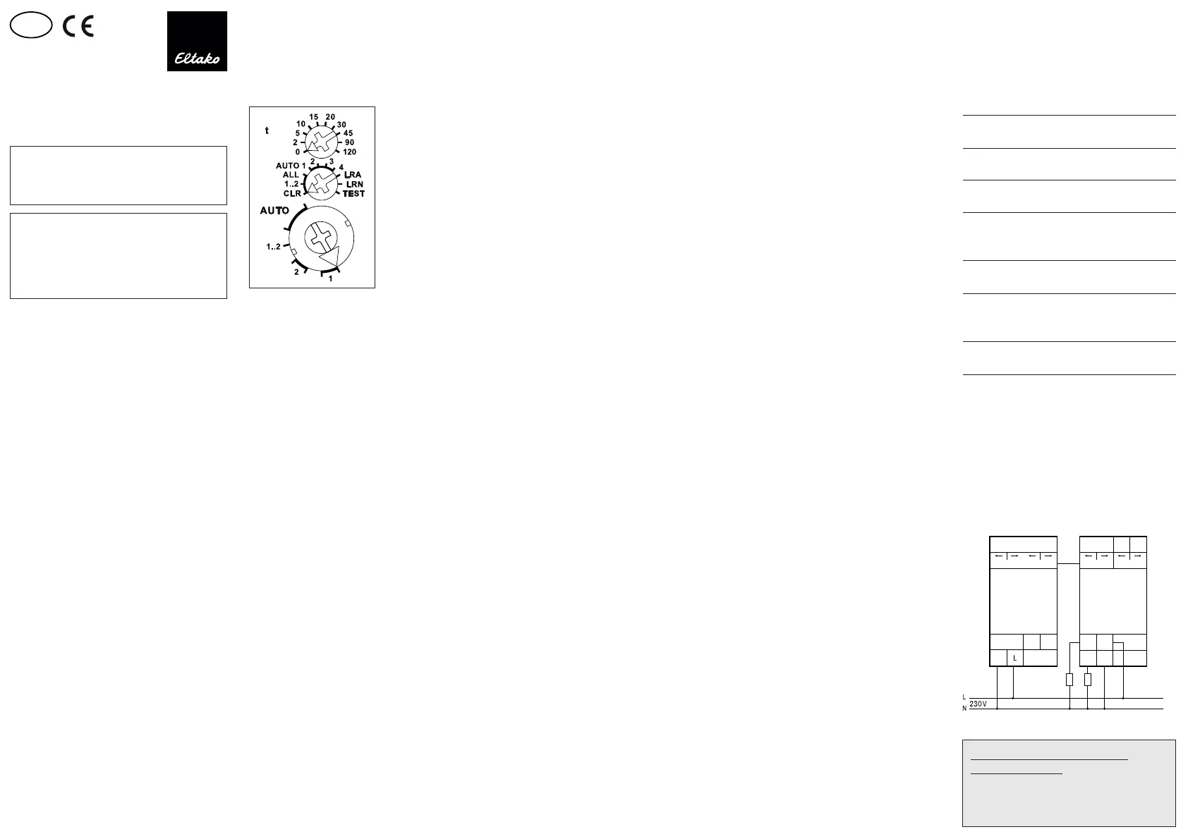
Function rotary switches
Use the rotary switches to teach-in the
buttons and test the 2 channels as required.
For normal mode, the middle and lower rotary
switches are then set to AUTO. With the
upper rotary switch the EW time (0-120 sec-
onds) is directly set for relays or the RV time
(0-120 minutes) for impulse switches for all
channels if necessary.
When FBH wireless motion/brightness sen-
sors (masters) (EEP A5-08-01) are taught-in,
the switching threshold is de ned separately
for each channel using the upper rotary
switch. The switching threshold switches the
lighting on or off depending on the bright-
ness (in addition to motion) (from approx.
30 lux in position 0 to approx. 300 lux in
position 90).
If FBH devices (slaves) are taught-in in Posi-
tion 120, they are only evaluated as motion
detectors.
Several FBH devices are interlinked per
channel. If an FBH signals 'motion', the NO
contact closes. Only when all FBH devices
signal 'no motion' does the NO contact open
after the preset RV time. When an FBH is
taught-in, the RV time only applies to the FBH.
Press the ON side of a direction push-button
for 2 seconds to switch it on permanently.
Signals are not evaluated by the FBH.
Press the OFF side of a direction pushbutton
for 2 seconds to switch it off permanently.
Signals are not evaluated by the FBH.
Press the direction pushbutton brie y to
re-evaluate FBH signals.
Wireless Building Visualisation and Control
Software GFVS. To do this, teach-in one or
several FSR14M-2x devices.
Semiautomatic motion detection with
taught-in wireless motion sensor FB65B
factory setting (EEP A5-07-01):Press the
pushbutton to switch on. This starts a
release delay time of 5 minutes during
which the device switches on again if motion
is detected. When no further motion is de-
tected, the device switches off automati cally
after 5 minutes in addition to the set RV time.
The actuator then reacts to motion for a
further 5 minutes and may switch back on
automatically. After this time expires, the
device must be switched on again by press-
ing the pushbutton. You can switch the
device off at any time by pressing the push-
button. Motion is then no longer evaluated.
Fully automatic motion detection with
taught-in wireless motion sensor FB65B:
If the actuator is not to switch on automati-
cally when motion is detected, e. g. in rooms
without daylight, replug the jumper to 'active'
on the FB65B device. When no further motion
is detected, the device switches off automat-
ically after a release delay time of 5 minutes
in addition to the set RV time. Press the
push button at any time to switch the device
on or off. When motion is detected, the
device switches on again automatically.
When wireless brightness sensors
(EEP A5-06-01, -02, -03)are taught-in, de ne
the switching threshold separately for each
channel using the top rotary switch. The
switching threshold switches the lighting on
or off depending on the brightness (from
approx. 0 lux in positi on 0 to approx. 50 lux
or 900 lux in position 120). A hysteresis of
approx. 300 lux is permanently set for switch
on/off.
An additionally set RV time is not taken into
account.
Only one FBH master or FHD60SB (EEP A5-
06-01) is taught-in per channel. However, one
FBH (masters) or FHD60SB (EEP A5-06-01)
can be taught-in in several channels.
When wireless window/door contacts FTK
(EEP D2-00-01, F6-10-00, A5-14-01, -03, -09, -0A)
are taught-in, different functions can be set
with the middle rotary switch in position
AUTO 1 to AUTO 4 and linked to maximum 116
FTKs:
AUTO 1 = window closed then output active.
AUTO 2 = window open then output active.
In settings AUTO 3 and AUTO 4 the FTKs
taught-in to a single channel are linked auto-
matically. With AUTO 3 all FTKs must be
closed so that the N/O contact closes (e. g.
for climate control). With AUTO 4 one open
FTK is su cient to close the N/O contact
(e.g. for an alarm signal or to switch on the
power supply for an extractor hood).
One or several FTKs can be taught-in in
several channels to allow several simultane-
ous functions in each FTK.
After a power failure the link is restored by a
new signal to the FTK and a signal on the
next status message 15 minutes later.
An additionally set RV time is not taken into
account.
Vibration sensor (EEP A5-14-05):
If the upper rotary switch was set to position
5 during teach-in, the actuator works as a
two-point switch, with 'vibration' it is
switched on, with 'no vibration' it is switched
off.
If the upper rotary switch was set to position
10 during teach-in, it is switched on with
'Vibration' and automatically switched off
after the time that can be set between 2 and
120 seconds has elapsed. If the upper rotary
switch is set to 0, it is not switched off auto-
matically, but must be switched off manually.
When
FRW, FRWB, FHMB (EEP A5-30-03)
wireless smoke alarms are taught-in, they are
interlinked per channel. When an FRW signals
'smoke', the NO contact closes. Only after all
FRW devices signal 'no smoke' does the NO
contact open.
When eco water probes FWS81 (EEP F6-05-01)
or con
oor water probes (Art. No. 78142) are
taught-in with FTM wireless transmitter (Art.-
No. 78143) from AFRISO, a variety of functions
can be set using the middle rotary switch in
Positions AUTO 1 to AUTO 4.
AUTO 1 = 'no water', then NO contact closed.
AUTO 2 = 'water', then NO contact closed.
In Positions AUTO 3 and AUTO 4 the water
probes taught-in to a single channel are
interlinked automatically. With AUTO 3, all
water probes must signal 'no water' before
the NO contact closes. The NO contact opens
when a water probe signals 'water'.
With AUTO 4, the NO contact closes when a
water probe signals 'water'. Only when all
water probes signal 'no water' does the NO
contact open.
An additionally set RV time is ignored.
The LED below the upper function rotary
switch performs during the teach-in process
according to the operation manual. It shows
control commands by short ickering during
operation.
Technical data
Rated switching capacity 16A/250V AC
each contact
2)
230V LED lamps up to 600 W
3)
I on ≤ 120 A/5 ms
Incandescent lamp and 2000 W
halogen lamp load
1)
230V
Fluorescent lamp load with KVG* 1000 VA
in lead-lag circuit or
non compensated
Fluorescent lamp load with KVG* 500 VA
shunt-compensated or with EVG*
Compact uorescent lamps 15x7 W
with EVG* and 10x20 W
energy saving lamps
Standby loss 0,9 W
(active power)
1
)
Applies to lamps of max. 150 W.
2)
The maximum current as a sum over both contacts is
16A, so a fuse with a maximum of 16A is required at L.
3)
Due to different lamp electronics and depending on
the manufacturer, the maximum number of lamps
may be limited, especially if the wattage of the
individual lamps is very low (e.g. with 2 W LEDs).
* EVG = electronic ballast units;
KVG = conventional ballast units
Typical connection
L
N
BUSBUS
2
1
N
Hold
FAM14
BUSBUS
Teaching-in wireless sensors in
wireless actuators
All sensors must be taught-in in the
actuators so that they can detect and
execute commands.
Product specificaties
| Merk: | Eltako |
| Categorie: | Niet gecategoriseerd |
| Model: | FSR14M-2x |
Heb je hulp nodig?
Als je hulp nodig hebt met Eltako FSR14M-2x stel dan hieronder een vraag en andere gebruikers zullen je antwoorden
Handleiding Niet gecategoriseerd Eltako

14 April 2025
14 April 2025
13 Maart 2024
21 Februari 2024
21 Februari 2024
21 Februari 2024
21 Februari 2024
20 Februari 2024
20 Februari 2024
20 Februari 2024
Handleiding Niet gecategoriseerd
Nieuwste handleidingen voor Niet gecategoriseerd
10 Maart 2026
10 Maart 2026
10 Maart 2026
10 Maart 2026
10 Maart 2026
10 Maart 2026
10 Maart 2026
10 Maart 2026
10 Maart 2026
10 Maart 2026