Eltako FRGBW14 Handleiding
Eltako
Niet gecategoriseerd
FRGBW14
Bekijk gratis de handleiding van Eltako FRGBW14 (4 pagina’s), behorend tot de categorie Niet gecategoriseerd. Deze gids werd als nuttig beoordeeld door 28 mensen en kreeg gemiddeld 5.0 sterren uit 14.5 reviews. Heb je een vraag over Eltako FRGBW14 of wil je andere gebruikers van dit product iets vragen? Stel een vraag
Pagina 1/4

Wireless actuator
PWM dimmer switch for LED
FRGBW14
GB
Temperature at mounting location:
-20°C up to +50°C.
Storage temperature: -25°C up to +70°C.
Relative humidity:
annual average value <75%.
30 014 068 - 1
Only skilled electricians may install this
electrical equipment otherwise there is
the risk of re or electric shock!
PWM dimmer switch with 4 channels for
LED 12-24 V DC, each up to 4 A. Adjustable
minimum brightness and dimming speed.
With snooze function and light alarm circuit.
Additionally with light scene control via
PC or with wireless pushbuttons.
Standby loss only 0.1 watt.
Modular device for DIN-EN 60715 TH35 rail
mounting. 2 modules = 36 mm wide, 58 mm
deep.
Connection to the Eltako-RS485 bus. Bus
cross wiring and power supply with jumper.
The set brightness level remains stored
when switched off (memory).
In case of a power failure, the switch position
and brightness level are saved and switched
on when the power supply is restored.
Automatic electronic overload protection and
overtemperature shutdown.
The upper rotary switch is only required
for teach-in.
Use the middle % rotary switch to set
the minimum brightness (fully dimmed).
Use the lower dimming speed rotary
switch to set the dimming speed.
The pushbuttons can either be taught in
as direction pushbuttons or universal
pushbuttons: as direction pushbutton,
one side is 'switch on and dim up'; the other
side is 'switch off and dim down'. A double-
click on the switch-on side triggers the auto-
matic dimming up to full brightness at dim-
speed. Doubleclick on the switch-off side to
trigger the snooze function.
As universal pushbutton, change the
direc-
tion by briefly releasing the pushbutton.
FBH wireless motion/brightness sensors
can be taught in as master or slave.
FAH wireless brightness sensors can be
taught in for switch-off dependent on
brightness or as a twilight switch.
Pushbutton 'central off' for 1 channel:
switches off.
Pushbutton 'central ON' for channel 1:
switches on with the memory value.
Pushbutton 'central off' for all 4 channels:
saves the current lighting scene and swit-
ches off.
Pushbutton 'central ON' for all 4 channels:
switches on with the light scene where cen-
tral was switched off most recently. After a
power failure, the memory values are swit-
ched on.
Rotary switch: Press the middle of the rotary
knob to switch on with the memory value and
to switch off and save the current dimming
value. Turn to the right (clockwise) to dim up.
The turning speed determines the dim-up
speed. If the dimming actuator was turned to
the right when it was switched off, the dimmer
will switch on at minimum brightness and
then continue to dim up. If the rotary knob is
turned jerkily – and the actuator was previously
switched on or off – dimup is rapid to full
brightness.
Turn to the left (anticlockwise) to dim-down
to the minimum brightness which is adjusted
on the dimming actuator.
The turning speed
determines the dim-down
speed. If the rotary
knob is turned to the left
jerkily, dim-down is rapid to the minimum
brightness which is adjusted on the dimming
actuator.
A rotary switch acting as intensity control
must be taught-in in all channels: Press or
turn to switch on. To dim up, turn to the
right and to dim down, turn to the left. Press
to switch off
.
A rotary switch acting as colour control
must be taught-in in all channels: Turn to
the right or left to switch on and change the
colour. Press to switch to white and press
again to change back to colour mode.
Colour and intensity double-rocker pushbut-
tons must be taught-in in all channels: Press
top part of right rocker to switch on and dim
up; press bottom part of right rocker to switch
off and dim down. Press top or bottom part of
left rocker to change the colour; press twice to
switch to white; press long to switch back to
colour mode.
Switching for light alarm clocks: An appro-
priately taught-in timer wireless signal starts
the wake-up function by switching on the
lighting at lowest brightness and slowly
dimming up to maximum brightness over a
period of 30 minutes (or light scene 5).
The dimming process is stopped by tapping
briefly, e.g. on the hand-held transmitter.
Snooze function (Univeral or direction push-
buttons must be taught-in in all channels):
With a double impulse the lighting is dimmed
down from the current dimming position to
the minimum brightness level and switched off.
The current dimming position as well as the
adjustable minimum brightness level determine
the dimming time (max. = 30 minutes) which
can be reduced as required. It can be switched
off at any time by short-time control com-
mands during the lighting is dimmed down.
Light scenes on the PC are set and retrieved
using the Wireless Visualisation and Control
Software GFVS. One or several FRGBW14
devices must be taught in on the PC as dim-
ming switches with percentage brightness
values or high-definition brightness values.
FBH as Master: When an FBH wireless motion
detector and brightness sensor is taught in,
the switching threshold at which the lighting
is switched on at the brightness values of
light scene 6 is defined during teach-in
using the lower rotary switch. The switching
threshold is dependent on the brightness in
addition to motion (from approx. 30 lux in
position OFF to approx. 300 lux in max position.
When the FBH in taught-in in the ON position,
it is only evaluated as a motion detector.
A time delay of 1 minute is a fixed setting in
the FBH.
By switching-off or dimming with pushbutton
,
the FBH is deactivated.
Central pushbutton, scene pusbhbutton and
'dimming value' by PC also lead to deactivation.
A short press on the switchon side of the
direction pushbutton, the FBH is reactivated.
FBH as Slave: The FBH is only evaluated as
motion detector.
FAH as Master: When a wireless brightness
sensor FAH is taught-in, the switching
threshold is defined by the lower rotary
switch during teach-in. The switching
threshold switches the lighting off depending
on the brightness. Switch-on is only possible
by pressing the pushbutton.
FAH as twilight switch: When an FAH wire-
less brightness sensor is taught in, the
switching threshold at which the lighting is
switched on at the brightness values of light
scene 6 is defined during teach-in using the
lower rotary switch. The switching threshold
is dependent on the brightness (from approx.
0 lux in position OFF to approx. 50 lux in max
position.
Switch-off takes place at a brightness of
> 200 Lux.
The red LED accompanies the teach-in
process and indicates control commands in
operation by flashing briefly.
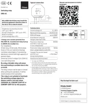
Typical connection
BUS BUS
N
Hold
FAM14
BUSBUS
230V AC
FSNT14
+12VGND
R G
-
+B W
12-24V DC
+
-
Teaching-in wireless sensors in
wireless actuators
All sensors must be taught-in in the
actuators so that they can detect and
execute commands.
Teaching-in actuator FRGBW14
The teach-in memory is empty on delivery
from the factory. To make sure that
nothing has already been taught-in, clear
the memory content completely:
Set the middle rotary switch to CLR.
The LED ashes at a high rate. Within the
next 10 seconds, turn the upper rotary
switch three times to the right stop (turn
clockwise) and then turn back away from
the stop. The LED stops ashing and
goes out after 2 seconds. All taught-in
sensors are cleared.
Clear individual taught-in sensors in the
same way as in the teach-in procedure,
except that you set the middle rotary
switch to CLR instead of LRN, and operate
the sensor. The LED previously flashing
at a high rate goes out.
Teaching-in sensors:
A total of 116 memory locations are
available.
1. Set the top rotary switch to the
required teach-in function.
1 = timer as wake-up light;
Teach-in FAH or FBH as Master
2 = 'central off';
Teach-in second FBH as slave
3 = universal switch;
Teach-in third FBH as slave;
4 = 'central on';
Teach-in fourth FBH as slave
5 = Teach in direction pushbutton;
Direction pushbutton are automatically
taught-in fully when pressed. Depending
on where the button is pressed, the
functions for switch-on and dim-up are
defined on one side and switchoff and
dim-down on the other side.
6 = teach in sequential light scene push-
button, a pushbutton or half of a double
pushbutton is assigned automatically.
7 = Teach in 4-way direct light scene
pushbuttons (a complete pushbutton
with double rocker is assigned automa-
tically). Turn the lower rotary switch to
the following position:
Function rotary switches


1 = light scene pushbutton for scenes 1-4
5 = light scene pushbutton for scenes 5-8
8 = Teach in FAH as twilight switch;
teach-in operating mode pushbutton;
teach in intensity rotary wheel
9 = Teach in GFVS and FFD with high
resolution dimming values; teach in
colour rotary wheel
10 =
Teach in rotary switch and GFVS;
during teach-in the actuator automatically
sends a confirmation telegram.
Teach in
dimming values of FFD; teach in colour
and intensity double rocker pushbutton;
Turn the lower rotary switch to the required
channel for universal pushbuttons, direction
pushbuttons and central control push-
buttons.
min = all 4 channels
1 = channel 1 (red),
2 = channel 2 (green),
3 = channel 3 (blue),
4 = channel 4 (white)
5 = multicolour pushbutton, a complete
pushbutton with double rocker is pro-
grammed automatically;
as universal pushbutton: top left =
channel 1 red, top right = channel 2
green, bottom left = channel 3 blue,
bottom right = channel 4 white;
as direction pushbutton left = channel 1
red, right = channel 2 green.
6 = multicolour pushbutton, a complete
pushbutton with double rocker is pro-
grammed automatically;
as direction pushbutton left = channel 3
blue, right = channel 4 white.
2.
Set the middle rotary switch to LRN.
The LED flashes at a low rate.
3. Operate the sensor to be taught-in.
The LED goes out
To prevent unintentional teach-in, turn the
rotary switch back to LRN for every teachin
process. The LED flashes at a slow rate.
Saving light scenes
Up to four brightness values retrievable
with a direct light scene pushbutton can be
saved.
1. Adjust the required brightness level with a
previously taught-in universal or direction
switch (separate for each channel if neces-
sary).
2. Within 60 seconds, press one of the four
rocker ends of the previously taught-in
direct light scene pushbutton for longer
than 3 seconds but less than 10 seconds
to save the brightness value.
3. Repeat from point 1 to save further light
scenes.
Retrieving light scenes
Up to 8 light scenes can be retrieved:
Direct light scene pushbutton 1-4 (pushbutton
with double rocker, top left = light scene 1,
top right = light scene 2, bottom left = light
scene 3 and bottom right = light scene 4).
Direct light scene pushbutton 5-8 (pushbutton
with double rocker, top left = light scene 5,
top right = light scene 6, bottom left = light
scene 7 and bottom right = light scene 8) and/
or with a sequential light scene pushbutton
(pushbutton or half a double pushbutton,
press top = next light scene, press bottom =
previous light scene).
Special modes:
The PCT14 can be used to change the
dimmer switch operating mode.
When special mode is activated (e.g. light
scene switch-through), the dimmer switch
is only switched on with Central ON, Central
OFF, FBH or FAH.
Operating modes:
■ 'Rotary switch' (factory setting)
■ 'Simple light scene switch-through':
Light scenes are activated (dimmed) in
the set sequence and time period. 8 light
scenes can be defined here.
Various effects can be generated using
the dimming speed and time setting.
LS1-LS2-LS3-LS4-LS5-LS6-LS7-LS8-
LS1…
■ 'Light scene switch-through with switch-
off': Light scenes and OFF are activated
(dimmed) alternately in the set time period.
LS1-AUS-LS2-AUS-LS3-AUS-LS4-AUS-
LS5-AUS-LS6-AUS-LS7-AUS-LS8-AUS-
LS1…
■ 'Light scenes in random sequence':
Light scenes are selected and activated
in random sequence in the set time period.
■ 'Random light scenes': Random events
are triggered in the set sequence.
An event may be a dim-up or dim-down
operation or a light scene.
Function of the operating mode pushbutton:
Press up:
normal mode ('rotary switch')
Press down:
special operating mode active
Assign device address for the FRGBW14:
The rotary switch on the FAM14 is set to
position 1, its lower LED ashes red.
The middle rotary switch of the FRGBW14 is
set to LRN, the LED ashes smothly. After
the address of the FAM14 was assigned, its
lower LED ashes green for 5 seconds and
the LED of the FRGBW14 goes out.
The FRGBW14 needs 6 device addresses.
4 device addresses for the feedback of the
% dimming values for channels 1-4.
Then the 2 device addresses follow for the
feedback for the button telegram (on/off)
and the high-resolution dimming value tele-
gram (both can be activated with PCT14).
Delete device con guration:
Set the middle rotary switch to CLR.
The LED ashes nervously.
Then turn the upper rotary switch within
10 seconds 3 times to the leftmost stop
(anticlockwise) and turn it back again.
The LED stops ashing and goes out after 5
seconds. The factory settings are restored.
Delete device con guration and device
address:
Set the middle rotary switch to CLR.
The LED ashes nervously.
Then turn the upper rotary switch within 10
seconds 6 times to the leftmost stop (anti-
clockwise) and turn it back again.
The LED stops ashing and goes out after 5
seconds. The factory settings are restored
and the device address deleted.
Configure FRGBW14:
The following points can be configured
using the PC PCT14 tool:
■ Teach in pushbuttons with single or
double click.
■ Behaviour after power failure
■ Minimum brightness
■ Brightness for light scenes
■ Preselect colour of light scenes
■ Operating mode
■ Time for special operating mode
■ Send dimming value in % : or OFFON
■ Send pushbutton telegram ON (0x70) and
OFF (0x50): OFF or ON
■ Confirmation telegrams
■ Confirmation flickering when scenes are
saved
■ PWM frequency (250Hz, 500Hz, 1kHz,
2kHz, 4kHz)
■ Dimming speeds
■
Dim-down delay for motion detector
■ Light alarm time period
■ Snooze function time period
■ Add or change sensors
Technical data
Supply voltage for LED 12-24V DC
Max current at PWM frequency
250Hz and 500Hz 4x 4A
1kHz 4x 3,2A
2kHz 4x 2,4A
4kHz 4x 1,6A
When an actuator is ready for
teach-in (the LED ashes at a low
rate), the very next incoming signal
is taught-in. Therefore, make
absolutely sure that you do not
activate any other sensors during
the teach-in phase.
!
Eltako GmbH
D-70736 Fellbach
Technical Support English:
+49 711 94350025
technical-support@eltako.de
eltako.com
30/2022 Subject to change without notice.
Must be kept for later use!
We recommend the housing for
operating instructions GBA14.
Manuals and documents in further
languages
http://eltako.com/redirect/FRGBW14
1. App 2. 3.
www.
Product specificaties
| Merk: | Eltako |
| Categorie: | Niet gecategoriseerd |
| Model: | FRGBW14 |
Heb je hulp nodig?
Als je hulp nodig hebt met Eltako FRGBW14 stel dan hieronder een vraag en andere gebruikers zullen je antwoorden
Handleiding Niet gecategoriseerd Eltako
14 April 2025
14 April 2025

13 Maart 2024

21 Februari 2024

21 Februari 2024

21 Februari 2024

21 Februari 2024

20 Februari 2024

20 Februari 2024

20 Februari 2024
Handleiding Niet gecategoriseerd
- Stromer
- Linear
- Coxreels
- Terratec
- SPC
- JennAir
- AURALiC
- Rollei
- Bugaboo
- Unilux
- Tecno
- Seymour Duncan
- Backyard Pro
- Balt
- Talkaphone
Nieuwste handleidingen voor Niet gecategoriseerd

1 Augustus 2025

1 Augustus 2025

1 Augustus 2025

1 Augustus 2025

1 Augustus 2025

1 Augustus 2025

1 Augustus 2025

1 Augustus 2025
1 Augustus 2025

1 Augustus 2025