Eltako FHK61U-230V Handleiding
Eltako Niet gecategoriseerd FHK61U-230V
Bekijk gratis de handleiding van Eltako FHK61U-230V (2 pagina’s), behorend tot de categorie Niet gecategoriseerd. Deze gids werd als nuttig beoordeeld door 185 mensen en kreeg gemiddeld 4.0 sterren uit 2 reviews. Heb je een vraag over Eltako FHK61U-230V of wil je andere gebruikers van dit product iets vragen? Stel een vraag
Pagina 1/2
1NO contact potential free10A/250V AC.
Only 0.8 watt standby loss. Encrypted
wireless, bidirectionalwireless and
repeater function are switchable.
For installation.
45mm long, 45mm wide, 33mm deep.
Supply voltage 230V.
If a power failure occurs, the switching
state is retained. If a power failure occurs
repeatedly, the device is switched off in a
defined sequence.
After installation, wait for short automatic
synchronisation before the switched
consumer is connected to the mains.
This heating/cooling relay evaluates the
information from wireless temperature
controllers or sensors. Possibly supple-
mented by window/door contacts, motion
detector, Hoppe window handles and
wireless pushbuttons.
Starting in production week11/14, you
can teach in encrypted sensors. You
can switch onbidirectional wireless
and/or arepeater function.
Every change in state of the contact is
confirmed by a wireless telegram. This
wireless telegram can be taught-in into
other actuators and the GFVS software.
Especially into a FSR61to synchronously
switch a heat circulating pump with the
valves.
GB
Only skilled electricians may install
this electrical equipment otherwise
there is the risk of fire or electric
shock!
Temperature at mounting location:
-20°C up to +50°C.
Storage temperature: -25°C up to +70°C.
Relative humidity:
annual average value <75%.
Wireless actuator
Heating/cooling relay
FHK61U-230V
30100 050 -2
valid for devices from production week
11/14 (see bottom side of housing)
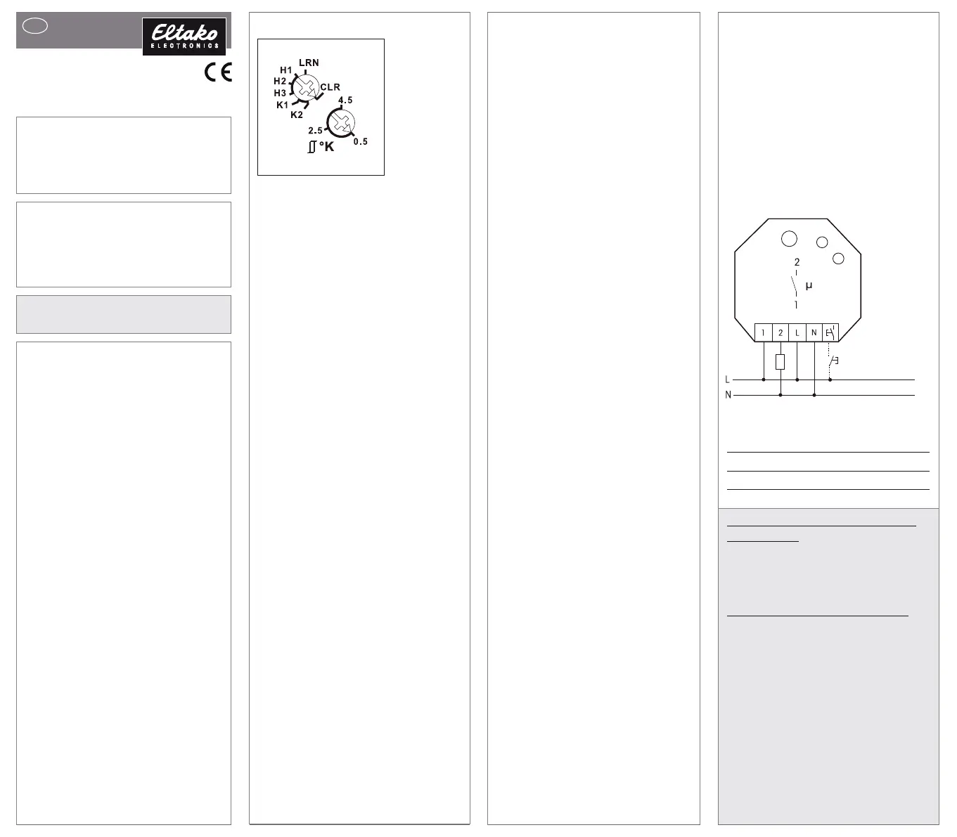
Function rotary switches
Top rotary switch for operating modes:
H1:Heating operation with PWM control
at T = 4 minutes. (suitable for valves
with thermoelectric valve drive)
H2: Heating operation with PWM control
at T =15 minutes. (suitable for valves
with motor-driven valve drive)
H3: Heating operation with 2-point
control.
K1: Cooling operation with PWM control
at T =15 minutes.
K2: Cooling mode with 2-point control.
Switchover is visualised by LEDs flashing.
Bottom rotary switch for adjustable
hysteresis and PWM influence:
Left stop:lowest hysteresis 0.5°.
Middle position:hysteresis 2.5°.
Right stop:largest hysteresis 4.5°.
Inbetween, divisions in steps of 0.5°
visualised by LEDs flashing.
Two-point control mode:
The hysteresis rotary switch sets the
required difference between the switch-on
and switch-off temperatures.
When the 'actual temperature >= reference
temperature', the device is switched off.
When the 'actual temperature <=
(reference temperature - hysteresis)', the
device is switched on. The signs are the
opposite in cooling mode.
PWM control mode:
The hysteresis rotary switch set the required
temperature difference at which the device
is switched on at100%. When the 'actual
temperature >= reference temperature',
the device is switched off.
When the 'actual temperature <=
(reference temperature - hysteresis)', the
device is switched on at100%.
If the 'actual temperature' lies between the
'reference temperature - hysteresis' and
the 'reference temperature', the device is
switched on and off with a PWM in steps
of10% depending on the temperature
difference.
The lower the temperature difference, the
shorter the switch-on time. As a result of
the settability of the100% value, the
PWM can be adapted to the heater size
and inertia. The signs are the opposite in
cooling mode.
In heating mode, the frost protection
functionis always enabled. As soon as
the actual temperature drops below 8°C,
the temperature is controlled in the
selected operating mode to 8°C.
If one or several windows are open, the
output remains off provided the window/
door contacts FTK or Hoppe handles
are taught-in. In heating mode, however,
the frost protection remains enabled.
As long as all taught-in motion detectors
FBHdetect no motion, the device is
switched to setback mode. In heating
mode, the reference temperature is set
back by 2°; in cooling mode, it is raised
by 2°. As soon as a motion detector
signals movement again, the device is
switched to normal mode.
When a wireless pushbutton is taught-in,
the assignment of the 4 keys is assigned
with the following fixed functions: Top
right: Normal mode (can also be enabled
by timer). Bottom right: Night setback
mode by 4°; in cooling mode, raised by
4° (can also be enabled by timer). Top
left: Setback mode by 2°, in cooling mode,
raised by 2°. Bottom left: Off (in heating
mode, frost protection enabled; in cooling
mode permanent off). If the motion
detector and wireless pushbutton are
taught-in at the same time, the last tele -
gram received is always the one that is
valid. A motion detector therefore switches
off a setback mode selected by wireless
pushbutton when a movement is detected.
Malfunction mode:
If a temperature sensor fails to receive a
wireless telegram for longer than1hour,
the LED lights up and the device switches
to fault mode. In heating mode, the device
remains switched on for1.2 minutes at H1
and switched off for 2.8 minutes. When
set to H2 and H3 the 'ON' time is 4.5
minutes and 'OFF' time is10.5 minutes.
Thedeviceisswitchedoffincooling
minutes
and
OFF
time
is10
.
5
minutes
.
The device is switched off in cooling
mode. When a wireless telegram is
again received, the LED goes out and the
device switches back to normal mode.
The LED performs during the teach-in
process according to the operation
manual. It shows wireless control
commands by short flickering during
operation.
Typical connection
Technical data
Rated switching capacity10A/250V AC
Standby loss (active power)0.8W
Teaching-in wireless sensors in wire
-
less actuators
All sensors must be taught-in in
actuators so that they can detect and
executetheir commands.
Teaching-in actuator FHK
61U-230V
The teach-in memory is empty on
delivery from the factory. To ensure that
a device was not previously taught-in,
clear the memory completely:
Turn the upper rotary switch to CLR.
The LED flashes at a high rate. Within
10 seconds, turn the lower rotary switch
three times to right stop (turn clockwise)
and back again. The LED stops flashing
and goes out after 2 seconds. All taught-
insensors are cleared; the repeater and
the confirmation telegrams are switched
off.
Product specificaties
| Merk: | Eltako |
| Categorie: | Niet gecategoriseerd |
| Model: | FHK61U-230V |
Heb je hulp nodig?
Als je hulp nodig hebt met Eltako FHK61U-230V stel dan hieronder een vraag en andere gebruikers zullen je antwoorden
Handleiding Niet gecategoriseerd Eltako

21 Juli 2026
20 Juli 2026
14 April 2025
14 April 2025
13 Maart 2024
21 Februari 2024
21 Februari 2024
21 Februari 2024
21 Februari 2024
20 Februari 2024
Handleiding Niet gecategoriseerd
Nieuwste handleidingen voor Niet gecategoriseerd
21 Juli 2026
21 Juli 2026
21 Juli 2026
21 Juli 2026
21 Juli 2026
21 Juli 2026
21 Juli 2026
21 Juli 2026
21 Juli 2026
21 Juli 2026