Eltako B4T55 Handleiding
Eltako Niet gecategoriseerd B4T55
Bekijk gratis de handleiding van Eltako B4T55 (1 pagina’s), behorend tot de categorie Niet gecategoriseerd. Deze gids werd als nuttig beoordeeld door 101 mensen en kreeg gemiddeld 4.3 sterren uit 9 reviews. Heb je een vraag over Eltako B4T55 of wil je andere gebruikers van dit product iets vragen? Stel een vraag
Pagina 1/1
GB
Bus pushbutton B4T55
30 000 290 -1
Bus pushbutton for single mounting
80x80x15mm. For connection to
FTS14TG pushbutton gateway.
Only 0.2 watt standby loss.
B4T55 bus 4-way pushbutton in
E-design, only16mm high.
The scope of supply comprises a mount-
ing base, an attachment frame with
snapped-on electronics, a frame R, a
rocker and a double rocker.
The double rocker permits entry of
4 evaluable signals, but the rocker
allows only 2 signals.
At the rear, a 20cm long red/black bus
line is routed externally. Red terminal to
BP, black to BN of a pushbutton gateway
FTS14TG.
Up to 30 bus switches and/or FTS61BTK
pushbutton bus couplers can be con-
nected to terminals BP and BN of an
FTS14TG pushbutton gateway. The per-
mitted maximum line length is 200m.
The RLC device enclosed with the
FTS14TG must also be connected to the
terminals BP and BN on the bus switch
or pushbutton bus coupler furthest away.
A voltage of 29V DC is supplied to the
connected B4 over a 2-wire pushbutton
bus which is also used for data transfer.
Please use only conventional bus or
telephone lines.
Confirmation telegrams from actuators
are displayed by 4 resp. 2 yellow LEDs
when the actuator IDs are entered by the
PCT14 in the ID table of the FTS14TG.
Use the sleeves in the 55mm socket box
for screw mounting.
Only skilled electricians may install
this electrical equipment otherwise
there is the risk of fire or electric
shock!
Temperature at mounting location:
-20°C up to +50°C.
Storage temperature: -25°C up to +70°C.
Relative humidity:
annual average value <75%.
Installation:Screw on mounting plate.
First attach the frame and then snap on
the mounting frame with the electronics
(labelling 0 must be above).When you
fit the rocker, the 0 mark on the rear
must always be on top.
We recommend stainless-steel counter-
sunk screws 2.9x25mm, DIN 7982 C,
for screw connections. Both with rawl
plugs 5x25mm and with 55mm switch
boxes.
Rocker:
top sends 0x70
bottom sends 0x50
Double rocker:
top left sends 0x30
bottom left sends 0x10
top right sends 0x70
bottom right sends 0x50
Operating mode rotary switches of the
FTS14TG:
Pos. 2, 3, 4: Every pushbutton of the
B4T55 has the same ID.
Recommended setting for ES functions
with direction pushbutton.
Pos. 5, 6, 7: Every pushbutton of the
B4T55 has a separate ID.
Prescribed setting with ER functions.
Issue device address for B4T55:
1.Connect the first B4T55 to the BP and
BN bus terminals.
The LED on the B4T55 lights up red.
2.Turn the rotary switch on the FTS14TG
to Pos.1.
After the FTS14TG issues the address,
its lower LED lights up green.
3.Turn the rotary switch on the FTS14TG
to Pos. 2 to 7.
The LED on the B4T55 lights up green.
4.Only then connect the second B4T55
and repeat the procedure from 2, etc.
A device address 0 (as-delivered state)
can only be issued to one B4T55.
The address is always issued in ascend-
ing order1-30.
When a B4T55 is replaced and the
rotary switch on the FTS14TG is turned to
Pos.1,the new B4T55 automatically re-
ceives the same device address and the
system runs as before without requiring
further teach-in.
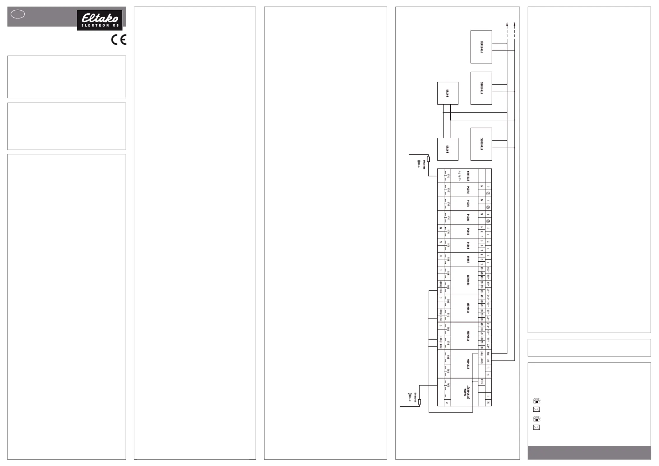
Typical connection
* alternatively FTS14KS without
bidirectional wireless
The second terminating resistor supplied
with the FAM14 or FTS14KS must be
plugged into the last bus user. Use the
PCT14 PC tool to make additional actuator
setting options for conventional pushbut-
tons. An FTS14TG pushbutton gateway
can be connected decentrally to up to
30 B4T55 bus switches and FTS61BTK
pushbutton bus couplers each with 4
pushbutton inputs. A single 2-wire line
supplies the pushbutton bus coupler with
power and also transfers the pushbutton
data. The user may select any topology
for the 2-wire connection.
Clear device address of a B4T55:
1. Connect only one B4T55 to the BP
and BN bus terminals.
The LED on the B4T55 lights up
green.
2. Turn the rotary switch on the
FTS14TG to Pos. 9.
After the device is cleared, the lower
LED on the FTS14TG lights up green
and the LED on the B4T55 lights up
red.
LED display:
LEDs off: There is no power supply over
the 2-wire bus.
Red LED lights up: Power is supplied
over the 2-wire bus. The B4T55 has no
device address yet or the bus is defective.
Green LED lights up: B4T55 has a de-
vice address and is ready to operate.
Use a jumper to disable the green LED off.
Eltako GmbH
D-70736 Fellbach
Technical Support English:
Michael Thünte +4917613582514
Marc Peter +49173 3180368
eltako.com
20/2017 Subject to change without notice.
Must be kept for later use!
Product specificaties
| Merk: | Eltako |
| Categorie: | Niet gecategoriseerd |
| Model: | B4T55 |
Heb je hulp nodig?
Als je hulp nodig hebt met Eltako B4T55 stel dan hieronder een vraag en andere gebruikers zullen je antwoorden
Handleiding Niet gecategoriseerd Eltako

14 April 2025
14 April 2025
13 Maart 2024
21 Februari 2024
21 Februari 2024
21 Februari 2024
21 Februari 2024
20 Februari 2024
20 Februari 2024
20 Februari 2024
Handleiding Niet gecategoriseerd
Nieuwste handleidingen voor Niet gecategoriseerd
9 Maart 2026
9 Maart 2026
9 Maart 2026
9 Maart 2026
9 Maart 2026
9 Maart 2026
9 Maart 2026
9 Maart 2026
9 Maart 2026
9 Maart 2026