Eltako FMZ14 Handleiding
Eltako Niet gecategoriseerd FMZ14
Bekijk gratis de handleiding van Eltako FMZ14 (2 pagina’s), behorend tot de categorie Niet gecategoriseerd. Deze gids werd als nuttig beoordeeld door 46 mensen en kreeg gemiddeld 4.7 sterren uit 9 reviews. Heb je een vraag over Eltako FMZ14 of wil je andere gebruikers van dit product iets vragen? Stel een vraag
Pagina 1/2
Multifunction time relay with10 functions,
1CO contact potential free10A/250V AC,
incandescent lamps 2000 watts*, with
DX technology. Bidirectional. Only 0.4 watt
standby loss.
Modular device for DIN-EN 60715 TH35
rail mounting.
1module =18mm wide, 58mm deep.
Connection to the Eltako-RS485 bus. Bus
cross wiring and power supply with jumper.
Wireless window contacts (FTK) and
window handles at opened
windows with
the function NO or NC can be taught-in.
Several FTK and (or) window handles
are linked to each other.If a direction
switch is taught-in, a function (e.g. TI)
can be started using the top switch
(START) and stopped with the bottom
switch (STOP).
Patented Eltako Duplex technology allows
youto switch normally potential free
contacts in zero passage switching when
230V A/C voltage 50Hz is switched.
This drastically reduces wear. To achieve
this, simply connectthe N conductor to
the terminal (N) and L toK(L). This
results in an additional standby
consumption of only 0.1watt.
If supply voltage fails, the two contacts
switch off. When power is restored,
contact1closes.
Tittibt05dd
GB
Only skilled electricians may install
this electrical equipment otherwise
there is the risk of fire or electric
shock!
Temperature at mounting location:
-20°C up to +50°C.
Storage temperature: -25°C up to +70°C.
Relative humidity:
annual average value <75%.
RS485 bus actuator
Multifunction time relay
FMZ14
30 014 009 -2
valid for devices from production week
40/17 (see bottom side of housing)
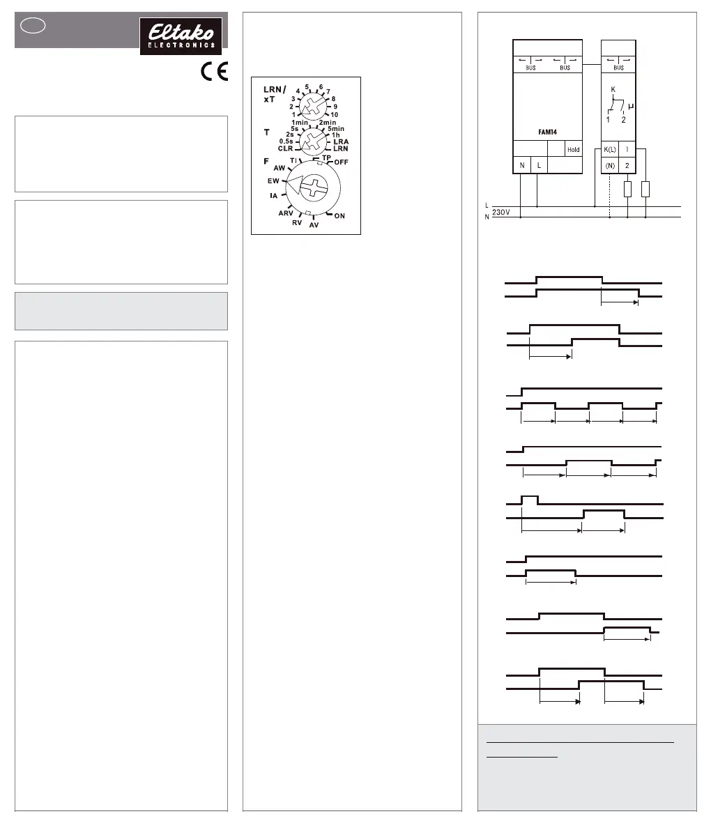
Typical connection
contact1closes.
Time setting between 0.5 second and
20 hours.
Function rotary switches
Teach-in takes place using the top and
middlerotary switchesand then the time
is set. T is the time base and xT the
multiplier.
The function is selected using the bottom
rotaryswitch:
RV= off delay
AV= operate delay
TI=
clock generator starting with impulse
TP= clock generator starting with pause
IA= impulse controlled operate delay
(e.g. automatic door opener)
EW= fleeting NO contact
AW= fleeting NC contact
ARV= operate and release delay
ON= Permanent ON
OFF= Permanent OFF
The LEDbelow the upper function rotary
switch performs during the teach-in
process
according to the operation man-
ual.
It shows control commands by short
flickering during operation.
* The maximum load can be used
starting at a delay time or clock cycle
of 5 minutes. The maximum load will
be reduced for shorter times as follows:
up to 2 seconds 15%, up to 2 minutes
30%, up to 5 minutes 60%.
Typical connection
Description of functions
t1t2t1t2
TI
Wireless
input
K(L)-2
t
t
ARV
Wireless
input
K(L)-2
t1 t2= 3s
IA
Wireless
input
K(L)-2
t
EW
Wireless
input
K(L)-2
Wireless
input
K(L)-2
AW
t
t1t2t1
TP
Wireless
input
K(L)-2
t
AV
Wireless
input
K(L)-2
Wireless
input
K(L)-2
t
RV
Teaching-in wireless sensors in wire-
less actuators
All sensors must be taught-in in the
actuators so that they can detect and
execute commands.
Product specificaties
| Merk: | Eltako |
| Categorie: | Niet gecategoriseerd |
| Model: | FMZ14 |
Heb je hulp nodig?
Als je hulp nodig hebt met Eltako FMZ14 stel dan hieronder een vraag en andere gebruikers zullen je antwoorden
Handleiding Niet gecategoriseerd Eltako

14 April 2025
14 April 2025
13 Maart 2024
21 Februari 2024
21 Februari 2024
21 Februari 2024
21 Februari 2024
20 Februari 2024
20 Februari 2024
20 Februari 2024
Handleiding Niet gecategoriseerd
Nieuwste handleidingen voor Niet gecategoriseerd
10 Maart 2026
10 Maart 2026
10 Maart 2026
10 Maart 2026
10 Maart 2026
10 Maart 2026
10 Maart 2026
10 Maart 2026
10 Maart 2026
10 Maart 2026