EK Water Blocks EK-FB ASUS R4BE Handleiding
EK Water Blocks Hardwarekoeling EK-FB ASUS R4BE
Bekijk gratis de handleiding van EK Water Blocks EK-FB ASUS R4BE (2 pagina’s), behorend tot de categorie Hardwarekoeling. Deze gids werd als nuttig beoordeeld door 41 mensen en kreeg gemiddeld 4.9 sterren uit 4 reviews. Heb je een vraag over EK Water Blocks EK-FB ASUS R4BE of wil je andere gebruikers van dit product iets vragen? Stel een vraag
Pagina 1/2
All disclosures, notices and warranty conditions are being written on EKWB web page. Please check terms of use. Revision 1.0. Published on December 20
th
2013
This product is intended for installation only by expert users. Please consult with a qualified technician for installation. Improper installation may result in damage to your equipment. EK Water Blocks assumes no liability
whatsoever, expressed or implied, for the use of these products, nor their installation. The following instructions are subject to change without notice. Please visit our web site at www.ekwb.com for updates. Before
installation of this product please read important notice, disclosure and warranty conditions printed on the back of the box.
Before you start using this product please follow these basic guidelines:
1.Please carefully read the manual before through before beginning with the installation process!
2.Please remove your motherboard from the computer to assure safest mounting process in order to prevent any possible damages to your CPU and/or motherboard’s circuit board (PCB).
3.The EK High Flow and EK-CSQ type fittings require only a small amount of force to screw them firmly in place since the liquid seal is ensured by the rubber o-ring gaskets.
4.The use of quality, market proved corrosion inhibiting coolants is always strongly recommended for any liquid cooling system.
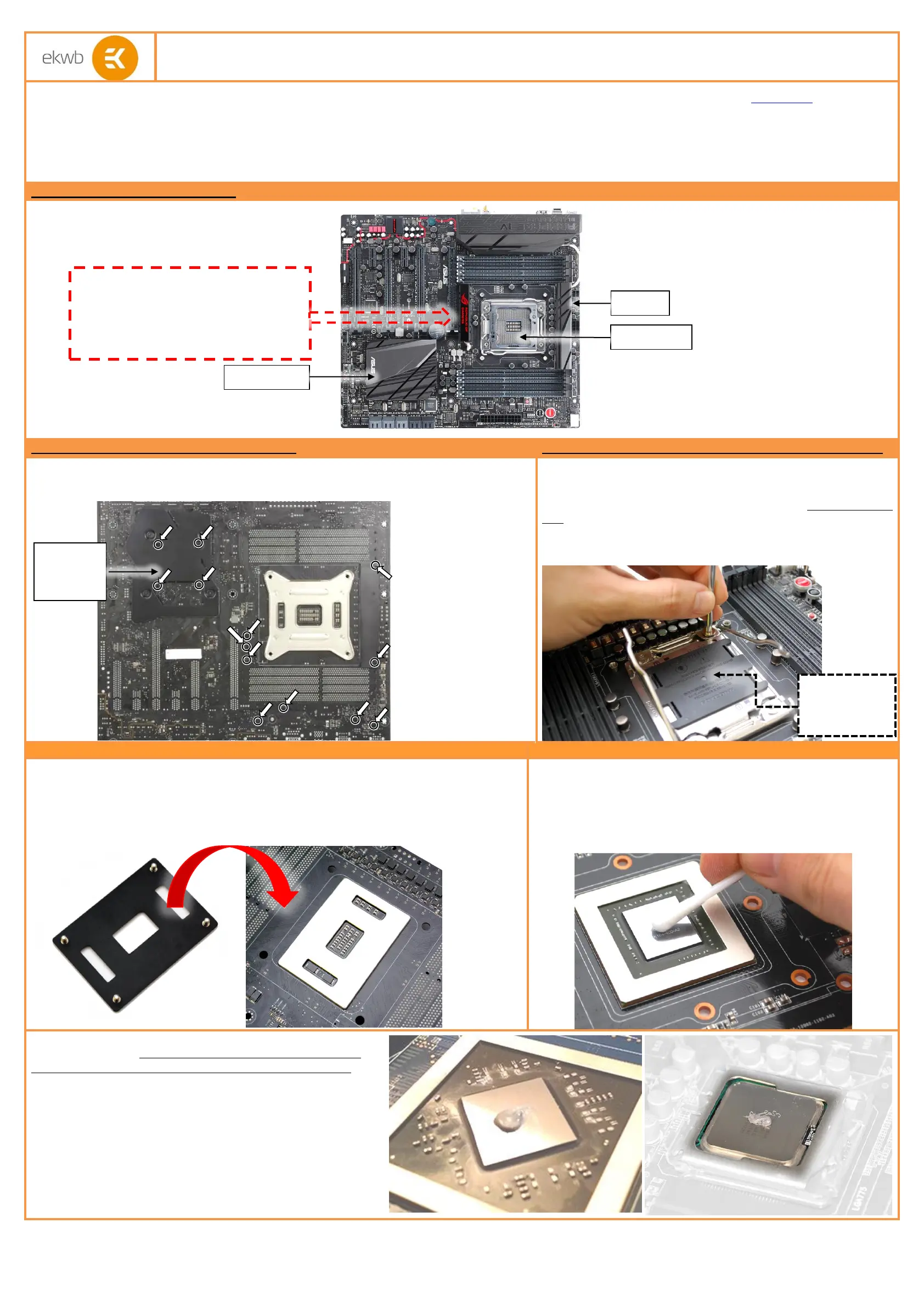
STEP 1: GENERAL INFORMATION Sample photo of ASUS Rampage IV Black Edition motherboard
STEP 1: PREPARING YOUR MOTHERBOARD
STEP 2: REMOVING THE ORIGINAL LATCH MECHANISM
BACKPLATE
1. REMOVING STOCK COOLER. Remove all encircled screws. There are 13 screws on the back of
the motherboard that needs to be removed in order to remove the factory installed SB/MOSFET heat
pipe cooling solution.
Please remove your motherboard from the computer to assure safest
mounting process possible in order to prevent any possible damages to
your PCB. With the enclosed Torx T20 key please remove all four (4)
screws securing the socket latch mechanism (ILM) to original backplate
(BP) to the motherboard. Make sure you have install the plastic
cover over the socket pins and that the socket latches are in
OPEN position during this procedure!
STEP 3: INSTALLING ALTERNATIVE LGA-2011 BACKPLATE
STEP 4: PREPARING YOUR MOTHERBOARD
After removing the original LGA-2011 backplate, installed on your ASUS Rampage IV Black Edition
motherboard, it is mandatory to install the alternative LGA-2011 provided with your motherboard.
Use the enclosed Torx T20 key to re-install it. Make sure you have install the plastic cover
over the socket pins and that the socket latches are in OPEN position during this
procedure! It is now a prime time to install your LGA-2011 CPU into the motherboard socket.
2.CLEANING THE PCB. Carefully detach the original stock cooler after
removing all screws securing it to the board. Wipe off the remains (by
using non–abrasive cloth or
qtip
, as shown on sample photo) of the
original thermal compound until the components and circuit board are
completely clean. EKWB recommends the use of denatured alcohol for
removing TIM leftovers.
3. APPLYING THERMAL COMPOUND. Apply thermal compound:
lightly coat the Intel X79 (PCH) – see sample photo on the left and
CPU heat spreader (IHS) - see sample photo on rightwith
enclosed EK-TIM Ectotherm thermal grease.
The quantity of about two rice grains is just about right. There is no need to cover the
whole IHS. Applying too much thermal grease will have negative impact on the cooling
performance!
Installation manual for EK-FB ASUS R4BE Monoblock water block
X79 PCH (SB)
CPU socket
Mosfets
IMPORTANT NOTICE:
ROG LED (Logo) has to be removed in order to
successfully complete installation of the FB KIT
ASUS R4BE and cannot be used in combination
with the FB KIT ASUS R4BE.
Use plastic
socket cover
during install!
Do not
remove the
X79 PCH (SB)
backplate!
Product specificaties
| Merk: | EK Water Blocks |
| Categorie: | Hardwarekoeling |
| Model: | EK-FB ASUS R4BE |
| Soort: | Waterblok |
| Compatibele producten: | ASUS Rampage IV Black Edition |
| Geschikte locatie: | Moederbord |
| Waterblok materiaal: | Koper |
Heb je hulp nodig?
Als je hulp nodig hebt met EK Water Blocks EK-FB ASUS R4BE stel dan hieronder een vraag en andere gebruikers zullen je antwoorden
Handleiding Hardwarekoeling EK Water Blocks

29 Maart 2025
29 Maart 2025
30 Juli 2024
19 Maart 2024
19 Maart 2024
19 Maart 2024
19 Maart 2024
19 Maart 2024
19 Maart 2024
19 Maart 2024
Handleiding Hardwarekoeling
Nieuwste handleidingen voor Hardwarekoeling
22 April 2026
21 April 2026
21 April 2026
12 April 2026
12 April 2026
11 April 2026
11 April 2026
11 April 2026
11 April 2026
6 April 2026