EK Water Blocks 3831109868966 Handleiding
EK Water Blocks Hardwarekoeling 3831109868966
Bekijk gratis de handleiding van EK Water Blocks 3831109868966 (2 pagina’s), behorend tot de categorie Hardwarekoeling. Deze gids werd als nuttig beoordeeld door 37 mensen en kreeg gemiddeld 4.8 sterren uit 6 reviews. Heb je een vraag over EK Water Blocks 3831109868966 of wil je andere gebruikers van dit product iets vragen? Stel een vraag
Pagina 1/2
All disclosures, notices and warranty conditions are being written on the EKWB website. Please read terms of use. Released on 20
th
of March, 2014. Revision 1.0
Installation and mounting manual for
EK-FC Titan Z (Original CSQ) water block
This product is intended for installation only by expert users. Please consult with a qualified technician for installation. Improper installation may result in damage to your equipment. EK Water Blocks assumes no liability
whatsoever, expressed or implied, for the use of these products, nor their installation. The following instructions are subject to change without notice. Please visit our web site at www.ekwb.com for updates. Before
installation of this product please read important notice, disclosure and warranty conditions printed on the back of the box.
Before you start using this product please follow these basic guidelines:
1.Please carefully read the manual before through before beginning with the installation process!
2.Please remove your motherboard from the computer to assure safest mounting process in order to prevent any possible damages to your CPU and/or motherboard’s circuit board (PCB).
3.The EK High Flow and EK-PSC type fittings require only a small amount of force to screw them firmly in place since the liquid seal is ensured by the rubber o-ring gaskets.
4.The use of corrosion inhibiting coolants is always recommended for any liquid cooling system.
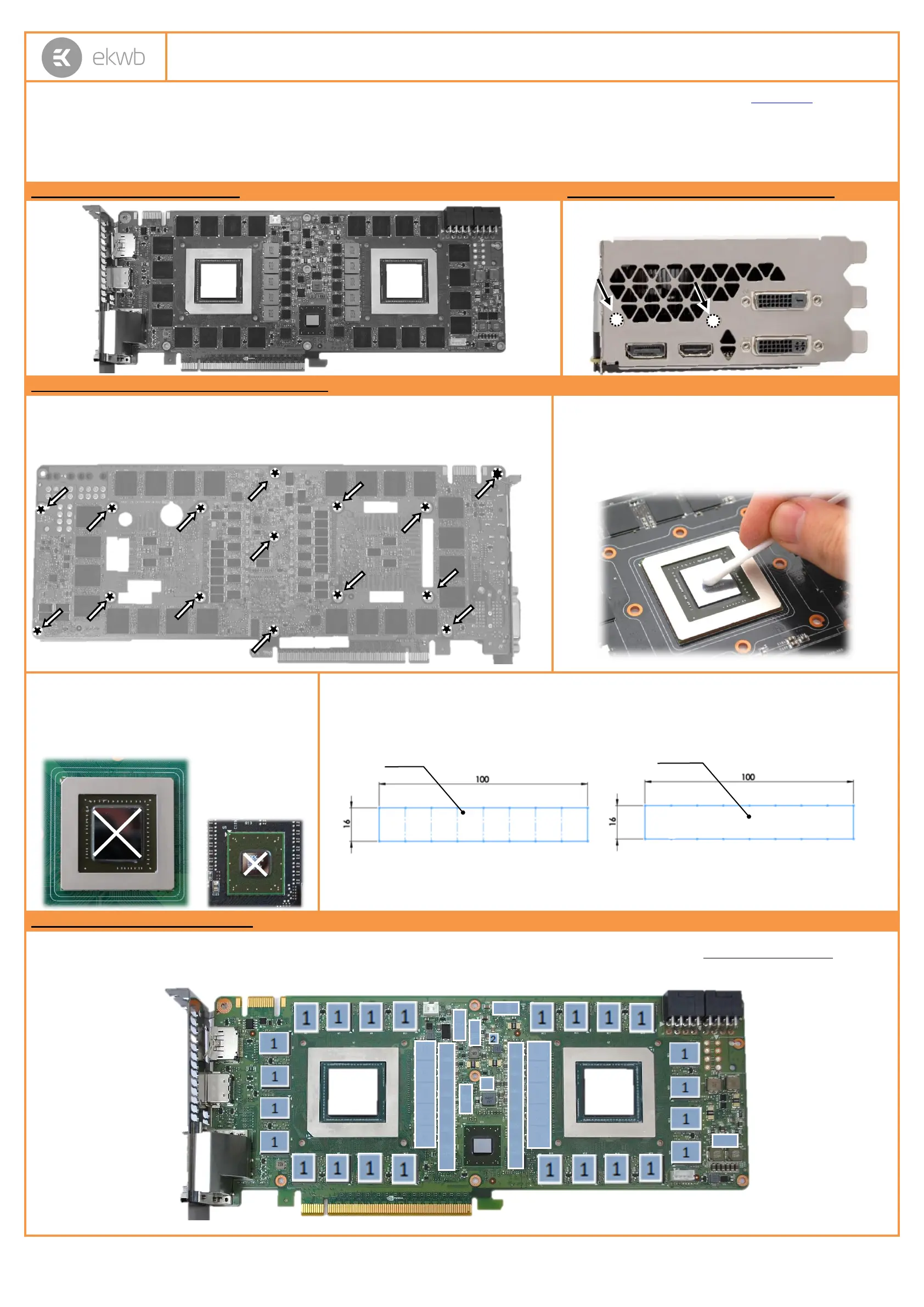
STEP 1: GENERAL INFORMATION.Sample picture of nVidia GeForce GTX Titan Z
STEP 2: PREPARING YOUR GRAPHIC CARD.
1. REMOVING STOCK COOLER and BRACKET: Remove encircled
screw on the bracket. Then remove all screws from bracket.
STEP 2 cont.: PREPARING YOUR GRAPHIC CARD
1 cont.. REMOVING STOCK COOLER. Remove all encircled screws. All heat sink assembly screws
should be removed, including self-adhesive washers on both sides of the PCB (if present). There are up to
19 screws on the back of the graphics card. After you remove the fan housing do not forget to unplug the
fan. You may need Torx T6 screwdriver instead of Philips head screwdriver (depending on manufacturer).
2. CLEANING THE PCB. Carefully detach the original stock cooler
after removing all screws securing it to the board. Wipe off the
remains (by using non–abrasive cloth or
qtip
, as shown on sample
photo) of the original thermal compound until the components and
circuit board are completely clean. EKWB recommends the use of
denatured alcohol for removing TIM leftovers.
3. APPLYING THERMAL COMPOUND. Apply thermal
compound: lightly coat both
nVidia
GPU chips as well as
PLX bridge chip with for example Arctic Cooling MX-2
™,MX-4 ™ or GELID GC-Extreme ™ thermal grease.
EKWB recommends to apply thermal grease in cross form
for best performance (see sample picture).
4. CUTTING THERMAL PADS. Your block comes with thermal pads, some of which are already pre-cut. Others
have to be cut to smaller chunks in order to cover all the VRM components such as MOSFETs and drivers. PLEASE
REMOVE THE PROTECTIVE FOIL FROM BOTH SIDES OF THE THERMAL PADS PRIOR TO INSTALLATION.
Replacement thermal pads: Thermal Pad A – 0.5mm (100x16mm), Thermal Pad D – 0.5mm (RAM 8X)
STEP 3: INSTALLING WATER BLOCK
1. PLACING THERMAL PADS ON PCB.Place thermal pads on chips so that numbers on chips match size of thermal pads. EKWB made sure users have more than
enough pads to cover all surfaces that need to be covered to make block fully functional). EKWB recommends using small drops of electrically non-conductive (for
example: Arctic Cooling MX-2 ™, MX-4 ™ or GELID GC-Extreme™) thermal grease on each phase regulator (that is being covered with thermal pad) in order to even
further improve the thermal performance of the EK-FC Titan Z series water block.
1: Thermal pad D– 0.5mm
(RAM):
1
1
1
1
1
1
1
1
2
2
2
1: Thermal pad A – 0.5mm
(for mosfet):
2
2
2
2
2
2
2
¸
2
Product specificaties
| Merk: | EK Water Blocks |
| Categorie: | Hardwarekoeling |
| Model: | 3831109868966 |
Heb je hulp nodig?
Als je hulp nodig hebt met EK Water Blocks 3831109868966 stel dan hieronder een vraag en andere gebruikers zullen je antwoorden
Handleiding Hardwarekoeling EK Water Blocks

29 Maart 2025
29 Maart 2025
30 Juli 2024
19 Maart 2024
19 Maart 2024
19 Maart 2024
19 Maart 2024
19 Maart 2024
19 Maart 2024
19 Maart 2024
Handleiding Hardwarekoeling
Nieuwste handleidingen voor Hardwarekoeling
22 April 2026
21 April 2026
21 April 2026
12 April 2026
12 April 2026
11 April 2026
11 April 2026
11 April 2026
11 April 2026
6 April 2026