Behringer Clocked Sequential Control Module 1027 Handleiding
Behringer
Synthesizer
Clocked Sequential Control Module 1027
Bekijk gratis de handleiding van Behringer Clocked Sequential Control Module 1027 (3 pagina’s), behorend tot de categorie Synthesizer. Deze gids werd als nuttig beoordeeld door 31 mensen en kreeg gemiddeld 4.9 sterren uit 16 reviews. Heb je een vraag over Behringer Clocked Sequential Control Module 1027 of wil je andere gebruikers van dit product iets vragen? Stel een vraag
Pagina 1/3

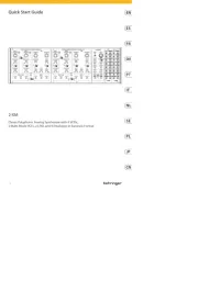
CLOCKED SEQUENTIAL
CONTROL MODULE 1027
Legendary 2500 Series 8-Position Step
Sequencer Module for Eurorack
Controls
(1) CH A / CH B / CH C SEQUENCER COLUMNS – Use the
knobs to set the control voltage output for each step.
Each column sends out control voltages via that channel’s
respective CH A / CH B / CH C output jack.
(2) STEP LEDs – Each LED lights to indicate its respective
sequencer step is active.
(3) POSITION GATES – Each of these output jacks sends out a
gate signal for its respective sequence step via cables with
3.5 mm TS connectors. These 8 gate output signals are
also available via the 12-pin GATE OUT LINK CONNECTOR
located on the module underside. This 12-pin connector
can connect to and trigger other compatible modules,
such as the MIX-SEQUENCER MODULE 1050, via a 12-pin
ribbon connector.
(4) RATE – This knob controls the step speed at which the
sequencer moves from step to step. The knob operates
in two overall frequency ranges determined by the
LOW/HIGH switch.
(5) LOW/HIGH – Use this sliding switch to set whether the
RATE knob operates in a lower-frequency (LOW) or
higher-frequency (HIGH) range.
(6) % PULSE WIDTH – Select between width settings
for the rectangular waveform ranging from 5% to 95%
duty cycle. The PULSE WIDTH control operates on the
CLK OUT jack only, making this control very useful for
triggering other modules such as envelope generators,
and so on.
(7) INT/EXT – Use this switch to select between internal (INT)
or external (EXT) pulse width control voltage. When EXT
is selected, the % PULSE WIDTH control knob is disabled.
(8) ON /OFF – This button starts or stops the sequence with a
manual button push.
(9) STEP – Press this button to manually progress to the next
sequencer step.
(10) RESET – Press this button to manually restart the
sequence at step 1.
(11) STEP – Use this jack to route external trigger signals for
the STEP button into the module via cables with 3.5 mm
TS connectors.
(12) RESET – Use this jack to route external trigger signals for
the RESET button into the module via cables with 3.5 mm
TS connectors.
(13) ON – Use this jack to route external trigger signals to
enable the step counter into the module via cables with
3.5 mm TS connectors.
(14) OFF – Use this jack to route external trigger signals to
disable the step counter into the module via cables with
3.5 mm TS connectors.
(15) RATE – Use this jack to route in external control voltage
signals for the sequencer's step speed (usually controlled
by the RATE knob) via cables with 3.5 mm TS connectors.
(16) WIDTH – This jack allows control voltage and modulation
signals for the rectangular waveform to be routed in via
cables with 3.5 mm TS connectors.
(17) CH A – This jack sends out control voltage signals for
the CH A sequencer column via cables with 3.5 mm
TS connectors.
(18) CH B – This jack sends out control voltage signals for
the CH B sequencer column via cables with 3.5 mm
TS connectors.
(19) CH C – This jack sends out control voltage signals for
the CH C sequencer column via cables with 3.5 mm
TS connectors.
(20) CLK OUT – Use this jack to export the internally generated
clock signal via cables with 3.5 mm TS connectors.
The internal clock produces a gate pulse every time
the sequencer steps, and the gate pulse’s width can be
adjusted using the % PULSE WIDTH control or via the
WIDTH control jack.
(1) (3)(2)
(4)
(5)
(6)
(7)
(8)
(9)
(13) (14)(15)(16) (17) (20)(18) (19)(12)
(10)
(11)
V 1.0
Quick Start Guide

Power Connection
The CLOCKED SEQUENTIAL CONTROL MODULE 1027 module comes
with the required power cable for connecting to a standard
Eurorack power supply system. Follow these steps to connect
power to the module. It is easier to make these connections before
the module has been mounted into a rack case.
1. Turn the power supply or rack case power o and
disconnect the power cable.
2. Insert the 16-pin connector on the power cable into the
socket on the power supply or rack case. The connector has
a tab that will align with the gap in the socket, so it cannot
be inserted incorrectly. If the power supply does not have
a keyed socket, be sure to orient pin 1 (-12 V) with the red
stripe on the cable.
3. Insert the 10-pin connector into the socket on the back of
the module. The connector has a tab that will align with the
socket for correct orientation.
4. After both ends of the power cable have been securely
attached, you may mount the module in a case and turn on
the power supply.
Installation
The necessary screws are included with the module for mounting in
a Eurorack case. Connect the power cable before mounting.
Depending on the rack case, there may be a series of xed holes
spaced 2 HP apart along the length of the case, or a track that allows
individual threaded plates to slide along the length of the case.
The free-moving threaded plates allow precise positioning of the
module, but each plate should be positioned in the approximate
relation to the mounting holes in your module before attaching
the screws.
Hold the module against the Eurorack rails so that each of the
mounting holes are aligned with a threaded rail or threaded
plate. Attach the screws part way to start, which will allow small
adjustments to the positioning while you get them all aligned. After
the nal position has been established, tighten the screws down.
Specications
Inputs
On / o
Type 2 x 3.5 mm TS jacks,
DC coupled
Impedance 100 KΩ, unbalanced
Maximum input level 10 V
Minimum switching
threshold
2.5 V, trigger
Rate
Type 1 x 3.5 mm TS jack,
DC coupled
Impedance 100 KΩ, unbalanced
Maximum input level 10 V, 1 V/oct.
Width
Type 1 x 3.5 mm TS jack,
DC coupled
Impedance 100 KΩ, unbalanced
Maximum input level 10 V
Step / reset
Type 2 x 3.5 mm TS jacks,
DC coupled
Impedance 100 KΩ, unbalanced
Maximum input level 10 V
Minimum switching
threshold
2.5 V
Outputs
Ch A / B / C
Type 3 x 3.5 mm TS jacks,
DC coupled
Impedance 1 KΩ, unbalanced
Maximum output level 10 V
Clock out
Type 1 x 3.5 mm TS jacks,
DC coupled
Impedance 1 KΩ, unbalanced
Maximum output level 5 V

Position gates
Type 8 x 3.5 mm TS jacks,
DC coupled
Impedance 1 KΩ, unbalanced
Maximum Output level 5 V
Controls
Rate 1 x rotary knob,
Low (0.3 Hz to 15 Hz)
High (10 Hz to 400 Hz)
% Pulse width 1 x rotary knob, 5% to 95%
Low / high 1 x sliding switch
Int / ext 1 x sliding switch
On / o 1 x button, LED backlit
Sequencer voltage knobs 24 x rotary knob, 0 V to 10 V
Step / reset 2 x momentary switch
Power
Power supply Eurorack
Current draw 70 mA (+12 V),
30 mA (-12 V)
Physical
Dimensions 43 x 162 x 129 mm
(1.7 x 6.4 x 5.1")
Rack units 32 HP
Weight 0.37 kg (0.81 lbs)
LEGAL DISCLAIMER
Music Tribe accepts no liability for any loss which may be suered by any
person who relies either wholly or in part upon any description, photograph,
or statement contained herein. Technical specications, appearances and
other information are subject to change without notice. All trademarks are the
property of their respective owners. Midas, Klark Teknik, Lab Gruppen, Lake,
Tannoy, Turbosound, TC Electronic, TC Helicon, Behringer, Bugera, Auratone
and Coolaudio are trademarks or registered trademarks of Music Tribe
Global Brands Ltd. © Music Tribe Global Brands Ltd. 2020 All rights reserved.
LIMITED WARRANTY
For the applicable warranty terms and conditions and additional information
regarding Music Tribe’s Limited Warranty, please see complete details online
at musictribe.com/warranty.
Product specificaties
| Merk: | Behringer |
| Categorie: | Synthesizer |
| Model: | Clocked Sequential Control Module 1027 |
Heb je hulp nodig?
Als je hulp nodig hebt met Behringer Clocked Sequential Control Module 1027 stel dan hieronder een vraag en andere gebruikers zullen je antwoorden
Handleiding Synthesizer Behringer
4 Juni 2025
1 April 2025
1 April 2025
1 April 2025
1 April 2025
1 April 2025
30 Januari 2025

2 Januari 2025
2 Januari 2025

2 Januari 2025
Handleiding Synthesizer
- GS Music
- IK Multimedia
- Korg
- X Audio Systems
- Twisted Electrons
- Fred's Lab
- Flame
- Nystrom
- Sonicware
- LennarDigital
- Yamaha
- Casio
- Omnitronic
- Native
- Make Noise
Nieuwste handleidingen voor Synthesizer

3 September 2025
1 September 2025

30 Juni 2025

10 Juni 2025
16 Mei 2025
13 Mei 2025
13 Mei 2025

12 Mei 2025

12 Mei 2025

12 Mei 2025