Behringer 921B Oscillator Handleiding
Behringer
Synthesizer
921B Oscillator
Bekijk gratis de handleiding van Behringer 921B Oscillator (15 pagina’s), behorend tot de categorie Synthesizer. Deze gids werd als nuttig beoordeeld door 117 mensen en kreeg gemiddeld 4.8 sterren uit 59 reviews. Heb je een vraag over Behringer 921B Oscillator of wil je andere gebruikers van dit product iets vragen? Stel een vraag
Pagina 1/15

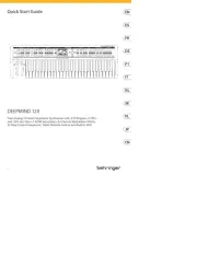
Quick Start Guide
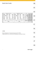
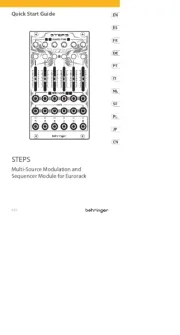
(EN) Controls
(6)
(7)
(8)
(5)
(1)
(2)
(3)
(4)
(9)
(1) FREQUENCY - This knob manually adjusts the frequency
in semitones for the 921B oscillator circuit. This oscillator
can generate both audio and sub-audio frequencies for
control or audio.
(2) RANGE - This knob sets the general frequency range of
the oscillator in octaves, numbered to match pipe organ
notations, which can then be adjusted up or down by
semitones with the FREQUENCY knob.
(3) 921AB LINK FREQ - These parallel jacks accept frequency
control voltage signals from a 921A module via cables with
3.5 mm TS connectors. The parallel wiring of the jacks also
allows a control voltage signal to be sent through and back
out to drive additional 921B modules.
(4) 921AB LINK WIDTH - These parallel jacks accept 921A
control voltage signals for the rectangular wave width
parameter via cables with 3.5 mm TS connectors. The
parallel wiring of the jacks also allows a control voltage
signal to be sent through and back out to drive additional
921B modules.
NOTE: If the 921B input voltage exceeds the range of 0 to
+6 V, the excess voltage could result in the width being
0% or 100%, which means no waveform will be present
at the square wave output until the control voltage is
returned to the normal range. When using 921B with a
921A driver, the 921A’s WIDTH OF RECTANGULAR WAVE
knob can oset the control voltage output from 921A to
compensate. For example, when 921A’s WIDTH knob is set
to 50%, the 921A’s normal control voltage range into 921B
becomes -3 V to +3 V.
(5) SYNC WEAK/OFF/STRONG - Use this switch to set how
closely 921B follows the sync signal routed in via the SYNC
IN jack. If the SYNC IN input is not required, select the
center OFF switch position.
(6) SYNC IN - Use this jack to route an external sync
signal into the 921B module via cables with 3.5 mm TS
connectors. A sawtooth waveform is recommended to
produce the best sync results.
(7) AC MOD - Use this AC-coupled input jack to control
frequency modulation via a control signal.
(8) DC MOD - Use this DC-coupled input jack to control
frequency modulation via a control signal.
(9) WAVEFORM OUTPUTS - Use these jacks to route oscillator
signals out of the module via cables with 3.5 mm jacks.
Four waveforms are available: sine, triangular, sawtooth
and rectangular.
Power Connection
The 921B OSCILLATOR module comes with the required power
cable for connecting to a standard Eurorack power supply system.
Follow these steps to connect power to the module. It is easier to
make these connections before the module has been mounted
into a rack case.
1. Turn the power supply or rack case power o and
disconnect the power cable.
2. Insert the 16-pin connector on the power cable into the
socket on the power supply or rack case. The connector has
a tab that will align with the gap in the socket, so it cannot
be inserted incorrectly. If the power supply does not have
a keyed socket, be sure to orient pin 1 (-12 V) with the red
stripe on the cable.
V 1.0
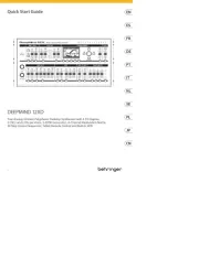
921B OSCILLATOR
Legendary Analog VCO
Module for Eurorack

c. Trim the SCALE trimmer to set 160 Hz, then remove
the -2 V input and readjust the FREQ ADJ trimmer
to 640 Hz.
d. Repeat this cycle until both 160 Hz and 640 Hz are
accurate to ±1 Hz when the -2 V is plugged in and
out of the 921AB LINK FREQ input jack.
5. Fine-tune the 921B oscillator’s high-frequency scaling via
the following steps:
a. With no 921AB LINK FREQ jack connected, check the
frequency is still set for 640 Hz output, then apply
exactly +5 V to the 921AB LINK FREQ input.
b. Trim the HI ADJ trimmer to set the 921B sawtooth
output to exactly 20.48 kHz.
c. Re-check that 640 Hz is still correct when the +5 V
input is removed.
d. Repeat as required.
6. Make a nal ne-tune of the RANGE rotary switch scaling,
if required, via the following steps:
a. With no 921AB LINK FREQ jack connected, check the
frequency is still set to 640 Hz on the RANGE knob
2’ setting.
b. Set the RANGE switch to 32’ and adjust the OCT ADJ
trimmer for 40 Hz at the 921B sawtooth output.
c. Re-check to make sure that 2’ = 640 Hz and
adjust the FREQ ADJ trimmer if required.
d. Repeat as required.
3. Insert the 10-pin connector into the socket on the back of
the module. The connector has a tab that will align with the
socket for correct orientation.
4. After both ends of the power cable have been securely
attached, you may mount the module in a case and turn on
the power supply.
Installation
The necessary screws are included with the module for mounting in a
Eurorack case. Connect the power cable before mounting.
Depending on the rack case, there may be a series of xed holes spaced
2 HP apart along the length of the case, or a track that allows individual
threaded plates to slide along the length of the case. The free-moving
threaded plates allow precise positioning of the module, but each plate
should be positioned in the approximate relation to the mounting
holes in your module before attaching the screws.
Hold the module against the Eurorack rails so that each of the
mounting holes are aligned with a threaded rail or threaded
plate. Attach the screws part way to start, which will allow small
adjustments to the positioning while you get them all aligned. After
the nal position has been established, tighten the screws down.
Tuning Procedure
This procedure tunes the 921B OSCILLATOR module’s “octave
scaling” to an exact 1 V/oct. calibration to facilitate precise control.
1. Power up the 921B module and allow it to warm up
for a few minutes.
2. Prepare the following control settings on 921B:
a. Set the SYNC toggle switch to the center
OFF position.
b. Set the RANGE switch to 2’.
c. Set the FREQUENCY control knob to exactly
0 on the scale.
d. Make sure no 921AB LINK FREQ jacks are connected.
Note: All adjustment trimmers are accessible from the 921B
module’s underside. Note the positions of the FREQ ADJ, SCALE,
HI ADJ multi-turn trimmers and the OCT ADJ single-turn trimmer.
Make sure you have suitable tools to adjust the trimmers
if required.
3. Carry out an initial FREQUENCY control calibration by
adjusting the FREQ ADJ trimmer so that the 921B sawtooth
output shows exactly 640 Hz when checked with an
accurate frequency meter.
4. Fine-tune the 921B oscillator’s low-frequency scaling via
the following steps:
a. Make sure the FREQUENCY control knob remains at 0
on the scale during this procedure.
b. Apply exactly -2 V to a 921AB LINK FREQ input jack.
(A 921A module can be used to supply the -2 V or use
a similar low-impedance stable-voltage source.)
2
921B OSCILLATOR

c. Ajuste el potenciómetro SCALE para establecer
160 Hz, luego retire la entrada -2 V y reajuste el
potenciómetro FREQ ADJ a 640 Hz.
d. Repita este ciclo hasta que tanto 160 Hz como 640 Hz
tengan una precisión de ± 1 Hz cuando se conecten
y desconecten -2 V del conector de entrada
921AB LINK FREQ.
5. Ajuste la escala de alta frecuencia del oscilador 921B mediante
los siguientes pasos:
a. Sin un conector 921AB LINK FREQ conectado,
verique que la frecuencia aún esté congurada para
una salida de 640 Hz, luego aplique exactamente +5
V a la entrada 921AB LINK FREQ.
b. Ajuste el potenciómetro HI ADJ para ajustar la salida
de diente de sierra del 921B a exactamente 20,48 kHz.
c. Vuelva a comprobar que 640 Hz sigue siendo correcto
cuando se quita la entrada de +5 V.
d. Repita según sea necesario.
6. Realice un ajuste no nal de la escala del interruptor giratorio
RANGE, si es necesario, mediante los siguientes pasos:
a. Sin un conector 921AB LINK FREQ conectado,
verique que la frecuencia aún esté congurada
en 640 Hz en el ajuste de la perilla RANGE 2'.
b. Coloque el interruptor RANGE en 32' y ajuste
el trimmer OCT ADJ a 40 Hz en la salida de diente
de sierra del 921B.
c. Vuelva a vericar para asegurarse
de que 2' = 640 Hz y ajuste el trimmer
FREQ ADJ si es necesario.
d. Repita según sea necesario.
Instalación
Los tornillos necesarios se incluyen con el módulo para el
montaje en una caja Eurorack. Conecte el cable de alimentación
antes del montaje.
Dependiendo de la caja del bastidor, puede haber una serie de
oricios jos separados 2 HP a lo largo de la caja, o una pista que
permita que las placas roscadas individuales se deslicen a lo largo
de la caja. Las placas roscadas de movimiento libre permiten un
posicionamiento preciso del módulo, pero cada placa debe colocarse
en una relación aproximada con los oricios de montaje en su
módulo antes de colocar los tornillos.
Sostenga el módulo contra los rieles Eurorack de modo que cada uno
de los oricios de montaje esté alineado con un riel o placa roscada.
Coloque los tornillos parcialmente para comenzar, lo que permitirá
pequeños ajustes en la posición mientras los alinea todos. Una vez
establecida la posición nal, apriete los tornillos.
Procedimiento de ajuste
Este procedimiento sintoniza el “escalado de octavas” del módulo
OSCILLATOR del 921B a un 1 V / oct exacto. Calibración para facilitar
un control preciso.
1. Encienda el módulo 921B y deje que se caliente durante
unos minutos.
2. Prepare los siguientes ajustes de control en el 921B:
a. Coloque el interruptor de palanca SYNC en la
posición central de APAGADO.
b. Coloque el interruptor RANGE en 2'.
c. Fije la perilla de control FREQUENCY exactamente
en 0 en la escala.
d. Asegúrese de que no haya conectores
921AB LINK FREQ conectados.
Note: Todos los potenciómetros de ajuste son accesibles desde la parte
inferior del módulo 921B. Observe las posiciones de los potenciómetros
multivueltas FREQ ADJ, SCALE, HI ADJ y del potenciómetro OCT ADJ de
una sola vuelta. Asegúrese de tener las herramientas adecuadas para
ajustar los recortadores si es necesario.
3. Realice una calibración inicial del control de FRECUENCIA
ajustando el potenciómetro FREQ ADJ de modo que la salida
de diente de sierra del 921B muestre exactamente 640 Hz
cuando se verique con un medidor de frecuencia preciso.
4. Ajuste la escala de baja frecuencia del oscilador 921B
mediante los siguientes pasos:
a. Asegúrese de que la perilla de control
FREQUENCY permanezca en 0 en la escala durante
este procedimiento.
b. Aplique exactamente -2 V a una toma de entrada
921AB LINK FREQ. (Se puede usar un módulo 921A
para suministrar los -2 V o usar una fuente similar de
voltaje estable de baja impedancia).
4921B OSCILLATOR
Product specificaties
| Merk: | Behringer |
| Categorie: | Synthesizer |
| Model: | 921B Oscillator |
Heb je hulp nodig?
Als je hulp nodig hebt met Behringer 921B Oscillator stel dan hieronder een vraag en andere gebruikers zullen je antwoorden
Handleiding Synthesizer Behringer
4 Juni 2025
1 April 2025
1 April 2025
1 April 2025
1 April 2025

1 April 2025
30 Januari 2025

2 Januari 2025

2 Januari 2025

2 Januari 2025
Handleiding Synthesizer
- Majella
- Roland
- Casio
- Yamaha
- Vermona
- Waldorf
- Studiologic
- Kodamo
- Sonicware
- Motas Electronics
- Meebleeps Machines
- Dnipro
- Noise Engineering
- LennarDigital
- Moog
Nieuwste handleidingen voor Synthesizer

3 September 2025

1 September 2025

30 Juni 2025

10 Juni 2025

16 Mei 2025
13 Mei 2025
13 Mei 2025

12 Mei 2025

12 Mei 2025

12 Mei 2025