WyreStorm TX-70-4K Handleiding


Lees hieronder de đź“– handleiding in het Nederlandse voor WyreStorm TX-70-4K (4 pagina's) in de categorie AV extender. Deze handleiding was nuttig voor 17 personen en werd door 2 gebruikers gemiddeld met 4.5 sterren beoordeeld

Pagina 1/4
4K HDBaseT Transmitter with PoH
TX-70-4K Quickstart Guide
Copyright © 2017 WyreStorm Technologies | wyrestorm.com
TX-70-4K Quickstart Guide | 170804
North America: 518-289-1294 | EMEA/ROW: 44 (0) 1793 230 343
support@wyrestorm.com
1 of 4
WyreStorm recommends reading through this document in its entirety to become familiar with the product’s features prior to starting the installation
process.
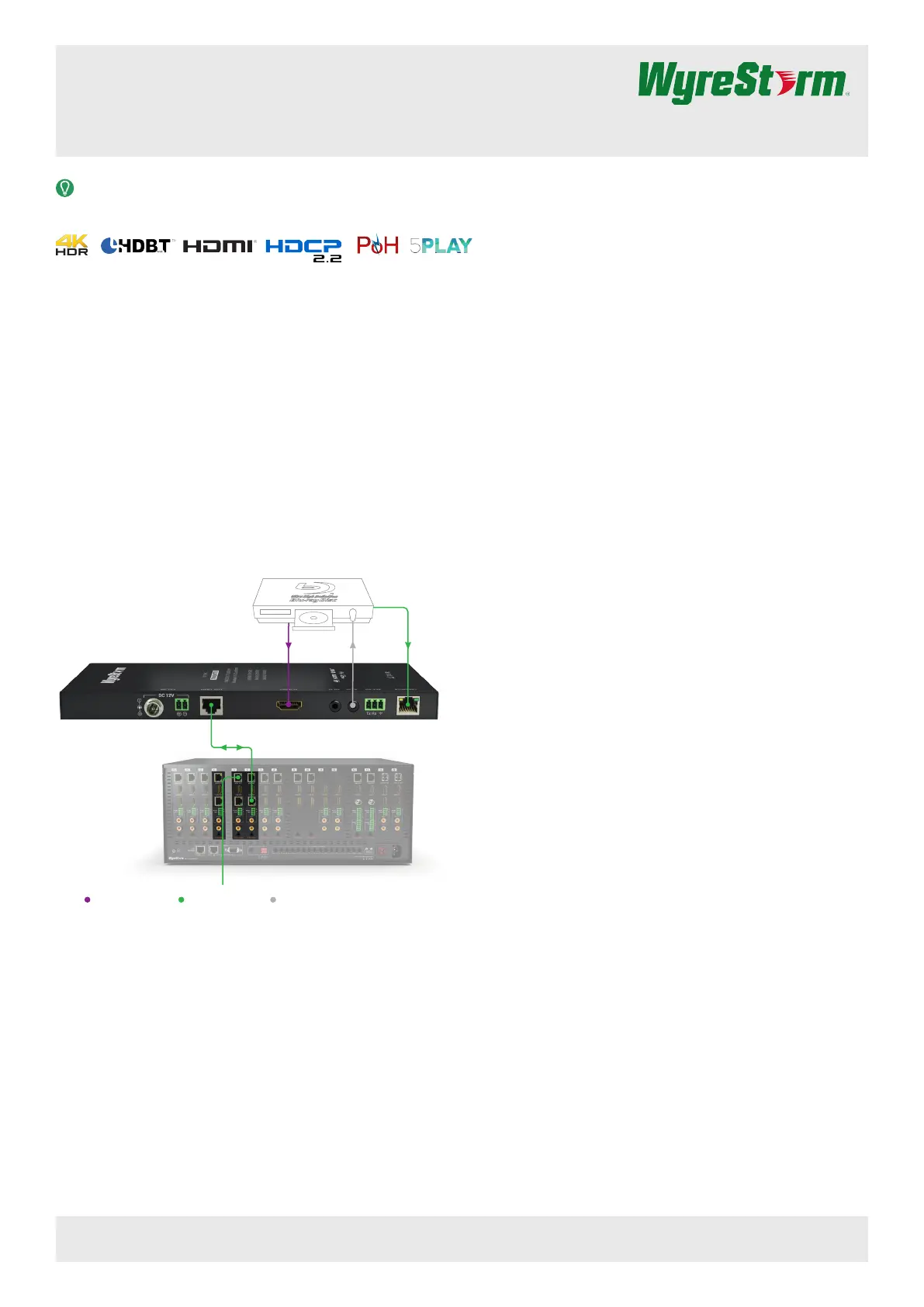
Basic Wiring Diagram
Before You Begin
• WyreStorm recommends visiting the product page before installing this
product for updates to this Quickstart Guide as well as other information
about the product.
• Verify that all items are included in the packaging per the In The Box list.
Associated Products
The TX-70-4K transmitter is designed to work with WyreStorm HDBT Input
cards as well as WyreStorm HDBaseT receivers allowing for flexibility in
system designs.
• H2X HDBaseT Matrix (with TX-H2X-HDBT card installed) – Allows for the
TX-70-4K to be used as a source on the matrix.
• RX-70-4K HDBaseT Receiver – Used when the output of the TX-70-4K is
going to a single display.
In The Box
1x TX-70-4K Transmitter
1x 3-pin Phoenix Connectors
1x Wide-band IR Emitter
1x Wide-band IR Receiver (30-50KHz)
2x Mounting Brackets
1x Quickstart Guide (this document)
IR
Key HDMI/Digital Video HDBaseT/Ethernet
TX-70-4K
MX-1616-HDBT-H2X
with TX-H2X-HDBT
UHD Source
HDBaseT Cat5e/6/6a
HDBaseT Cat5e/6/6a
HDMI IR Emitter Ethernet
Front Panel
Rear Panel
Copyright © 2017 WyreStorm Technologies | wyrestorm.com
TX-70-4K Quickstart Guide | 170804
North America: 518-289-1294 | EMEA/ROW: 44 (0) 1793 230 343
support@wyrestorm.com
2 of 4
A B C D E F
A B C D E F
Set (TX) 3 Position Dipswitch
Used to enable/disable long cable mode and congure RS-232 port operation. See Set Switch section for operation.
EDID 3 Position Dipswitch
Used to set EDIDs to correct resolution conflicts between the source and the display. See section for operation.EDID Settings
Power LED Solid: The receiver is powered On
Off: The receiver is powered Off
Status LED Flashing: The receiver is operating normally.
Off: The receiver is Not operating normally.
HDCP LED
Solid: HDCP content is present.
Flashing: HDCP content is not present.
Off: No signal.
LINK LED Solid: Link to receiver has been established.
Flashing: Link to receiver has not been established.
Power Input 5.5mm Screw Down Barrel Jack
2-pin Phoenix Connecter
HDBT Out 8-pin RJ-45 female
HDMI In 19-pin type A HDMI female | Supports HDMI and DVI/D with adapter
IR TX
IR RX
IR TX - 3.5mm (1/8in) Mono Jack: Connect to the supplied IR emitter to control a local device from the remote display location
via HDBaseT.
IR RX - 3.5mm (1/8in) Stereo Jack: Connect to the supplied IR receiver to send IR to the remote display location via HDBaseT.
See for more information.IR Wiring
RS-232
3-pin Phoenix Connector
Used to transmit RS-232 over HDBaseT to the remote location and for rmware updates.
See section for more information.RS-232 Wiring
Ethernet 8-pin RJ-45 female | 10/100 Mbps auto-negotiating
Connect to a Local Area Network or network device for Ethernet pass-through via HDBaseT.
Copyright © 2017 WyreStorm Technologies | wyrestorm.com
TX-70-4K Quickstart Guide | 170804
North America: 518-289-1294 | EMEA/ROW: 44 (0) 1793 230 343
support@wyrestorm.com
3 of 4
Wiring and Connections
WyreStorm recommends that all wiring for the installation is run and terminated prior to making connections to the switcher. Read through this section in this
entirety before running or terminating the wires to ensure proper operation and to avoid damaging equipment.
IMPORTANT! Wiring Guidelines
• The use of patch panels, wall plates, cable extenders, kinks in cables, and
electrical or environmental interference will have an adverse effect on HDMI
and Ethernet transmission limiting performance. Steps should be taken to
minimize or remove these factors completely during installation for best
results.
• WyreStorm recommends using high quality HDMI cables such as
WyreStorm Express to ensure the highest content performance available.
• The type of category cable and length used can restrict the available video
resolution. While Cat5e can be used, WyreStorm recommends using Cat6
or higher to ensure the highest content performance available. See Video
Resolutions in the table before determining cable type and Specications
length.
HDMI Wiring
WyreStorm recommends using pre-terminated HDMI cables due to the
complexity of these connector types. Using pre-terminated cables will ensure
that these connections are accurate and will not interfere with the performance
of the product.
HDBaseT Wiring
Pin 1
Pin 8
Wire colors shown follow EIA/TIA-568B standard.
Pin 1:
Pin 2:
Pin 3:
Pin 4:
Pin 5:
Pin 6:
Pin 7:
Pin 8:
White/Orange
Orange
White/Green
Blue
White/Blue
Green
White/Brown
Brown
IR Wiring
IMPORTANT! IR TX/RX Guidelines
• WyreStorm IR ports function differently than standard IR ports. For this
reason only WyreStorm IR emitters and receivers can be used.
• WyreStorm IR emitter and receiver cables cannot be spliced as cutting
into the cables will short the shield. While an extension cable may be used,
WyreStorm assumes no responsibility for operation using an extension
cable.
• When connecting the IR TX to an IR connecting blocks or control system
with different plugs, a cable must be made following the IR TX Port Pinout
diagram.
• When connecting to an IR control system use the WyreStorm CAB-IR-LINK
cable. This cable compensates for differences between the WyreStorm RX
and the control systems TX connection. Visit the WyreStorm CAB-IR-LINK
product page for details.
IR TX Port Pinout
Tip: Anode/5V
Sleeve: Cathode/IR Signal
IR RX Port Pinout
Tip:
Ring: IR Signal
+5V DC
Sleeve: Ground (GND)
RS-232 Wiring
Most control systems and computers are DTE where pin 2 is RX, this can vary
from device to device. Refer to the documentation for the connected device
for pin functionally to ensure that the correct connections can be made.
1 2 3
Pin 1:
Pin 2:
TX (Transmit)
RX (Receive)
Pin 3: Ground (GND)
Setup and Conguration
Set Switch
Note: Switches shown in gray can be in any position for the described setting.
RS-232 Pass-through
(default) 123
ON
HDBaseT Update
Updates to the HDBT chip 123
ON
Firmware Updates
Allows for updating the
extenders rmware
123
ON
Long Cable Mode On
Extends transmission of
HDBT up to 140m/439ft
123
ON
Long Cable Mode Off
Maintains standard HDBT
distances
123
ON
EDID Settings
EDID Copy 4K @60Hz 2ch
1080p @60Hz 2ch 1080i @60Hz 2ch
1080p @60Hz 5.1ch 1080p @60Hz 7.1ch


Product specificaties

Merk: WyreStorm
Categorie: AV extender
Model: TX-70-4K
Kleur van het product: Zwart
Gewicht: 520 g
Breedte: 220 mm
Diepte: 89.9 mm
Hoogte: 24.9 mm
Soort: AV-zender
LED-indicatoren: Ja
Connectiviteitstechnologie: Bedraad
Ethernet LAN: Ja
Ondersteunde video-modi: 1080p, 2160p
Maximum resolutie: 4096 x 2160 Pixels
Snelstartgids: Ja
Vermogensverbruik (max): 26.5 W
Certificering: FCC, CE
HDCP: Ja
Ondersteunde grafische resoluties: 1920 x 1080 (HD 1080),3840 x 2160,4096 x 2160
Remote (IR) ingang: 1
Duurzaamheidscertificaten: RoHS
Kleurdiepte: 12 Bit
Temperatuur bij opslag: -20 - 70 °C
Output current: 2 A
Remote (IR) uitgang: 1
HDMI in: 1
RS-232 ingangspoorten: 1
RJ-45 uitgang ports: 1
Montagebeugels meegeleverd: Ja
RJ-45 invoer ports: 1
HDBaseT-poort: Ja
Maximaal bereik: 70 m
AC-ingangsspanning: 100 - 240 V
AC-ingangsfrequentie: 50 - 60 Hz
Bedrijfstemperatuur (T-T): 0 - 45 °C
Relatieve vochtigheid in bedrijf (V-V): 10 - 90 procent
Ondersteundende kabel types: Cat6, Cat6a, Cat7
Bedrijfsspanning (zender): 12 V

Heb je hulp nodig?

Als je hulp nodig hebt met WyreStorm TX-70-4K stel dan hieronder een vraag en andere gebruikers zullen je antwoorden


Handleiding AV extender WyreStorm

Handleiding AV extender

Nieuwste handleidingen voor AV extender