PECO SB200-001 Handleiding
PECO
Thermostaat
SB200-001
Bekijk gratis de handleiding van PECO SB200-001 (2 pagina’s), behorend tot de categorie Thermostaat. Deze gids werd als nuttig beoordeeld door 25 mensen en kreeg gemiddeld 4.8 sterren uit 13 reviews. Heb je een vraag over PECO SB200-001 of wil je andere gebruikers van dit product iets vragen? Stel een vraag
Pagina 1/2

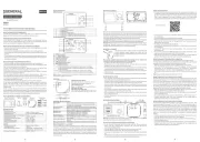
INSTALLATION & WALK TEST
GENERAL
The SB200-001 is an occupancy sensor designed for
automatic HVAC system control. This sensor provides a
changeover (form C) relay signal output for fan coil controller
to activate/deactivate the operation of fan coil automatically.
This sensor can be wall or corner mounted with 110°, 50 ft
(15m) detection range.
INSTALLATION & WALK TEST
Installation
1. Mount the base of mounting bracket on the selected
position. Route the cable through the access tunnel
of mounting bracket.
2. Open the front cover by loosening the locking screw
at the bottom. Route the cable into the unit and
assemble the mounting bracket with the unit.
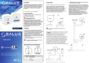
Wiring Diagram
NC-COM-NO: Output for ON-
OFF control of fan coil operation.
Dry contact signal.
24 V: Power supply (non-polarity)
4. Replace the front cover and then perform the walk
test.
Walk Test
Apply the power supply to the sensor and wait for about 45
seconds to warm unit up. The LED will blink (long-short)
during warm up period. Ensure the jumper head connectors
of ON and OFF delays are placed on “A” position (shortest
delay). Walk across the detection zones (invisible) at normal
speed. The LED will light whenever the sensor detects the
motion. Note: If any jumper is not properly placed, the LED
will blink.
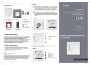
Ceiling Mount
Wall Mount
© Copyright 2004 PECO, Inc. All Rights Reserved P/N 68737 3220-1386 Rev1 Page 1
Do not install where unit is
exposed to direct sunlight or
directly above strong sourcesof
heat.
Make sure the detection area does
not have any obstruction (plants,
large pieces of furniture, curtains
etc.) which may block the
detection.
INSTALLATION HINTS
3. Connect the cable to the corresponding terminals
according to the following instructions.
DESCRIPTION
Installation Instructions
SB200-001
HVAC Occupancy Sensor

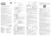
OPERATION
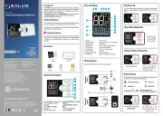
Operation Diagram
A. Standby
After warm up period expires, the
sensor enters into standby mode.
Sensor will check if delay jumpers
are properly placed. If not, the LED
will flash.
B. Relay ON Delay
Relay ON delay is the time given
to sensor to verify true occupancy
before activating the relay output.
Any further detection during ON
delay will NOT reset the timer.
C. 1-minute Waiting
When Relay ON delay expires, the
sensor enters into a 1-minute
waiting time. If no detection within
1 minute, then sensor will return to
standby mode. If any detection
occurs, then relay output will be
activated and Relay OFF delay will
be started.
D. Relay OFF Delay
Relay OFF delay is the time of
relay activating. Every detection
during this period will reset the
timer.
RANGE ADJUSTMENT
In order to suit different rooms or areas, the detection range of
SB200-001 can be adjusted by changing the direction of the
sensor. To change the sensor direction, release the screw on
the mounting bracket and then carefully move the sensor to the
direction desired.
ON / OFF DELAY
The ON and OFF delays are designed to provide intelligent energy
management of the HVAC system. ON delay is the time given to
the sensor to certify the occupancy, before it activates the fan
controller. OFF delay is the time that relay is active. Both ON and
OFF delays can be easily set by placing the jumper on the
corresponding pins as follows:
DETECTION PATTERN
SPECIFICATIONS
A.
Standby
B.
Relay ON
Delay
C.
1-Minute
Waiting
D.
Relay OFF
Delay
(Relay Output)
A B C D E F
ON 0 sec. 10 sec. 30 sec. 1 min. 5 min. 10 min.
OFF 10 sec. 1 min. 5 min. 10 min. 20 min. 30 min.
•READ THESE INSTRUCTIONS CAREFULLY BEFORE
ATTEMPTING TO INSTALL, OPERATE OR SERVICE THIS
DEVICE.
•Failure to observe safety information and comply with
instructions could result in PERSONAL INJURY, DEATH AND/
OR PROPERTY DAMAGE.
•To avoid electrical shock or damage to equipment, disconnect
power before installing or servicing.
•To avoid potential fire and/ or explosion do not use in potentially
flammable or explosive atmospheres.
•Retain these instructions for future reference. This product,
when installed, will be part of an engineered system whose
specifications and performance characteristics are not designed
or controlled by PECO, Inc. You must review your application
and national and local codes to assure that your installation
will be functional and safe.
WARNING
Use Copper wire only, insulate or wire nut
all un-used leads.
CAUTION
No
detection
Detection
Detection
Power supply…………...24 ± 2 V AC/DC
Detection range………..110°, 15 x 15 m at 25°C
Output format…………..Form C, 30 VDC, 0.2A max.
Current drain.................Standby: 5 mA Active: 18 mA
Mounting height…………1.8~3.6 m
Mounting bracket………..MB-99
Detectable speed………..0.1~3.0 m/sec.
RFI immunity…………….Av. 20 V/m (10~1,000 MHz)
Temperature…………….-20°C~38°C (-4°F ~ 100°F)
Humidity…......................95% RH max.
Dimensions.....................112 x 66 x 45 mm
© Copyright 2004 PECO, Inc. All Rights Reserved P/N 68737 3220-1387 Rev1 Page 2
Product specificaties
| Merk: | PECO |
| Categorie: | Thermostaat |
| Model: | SB200-001 |
Heb je hulp nodig?
Als je hulp nodig hebt met PECO SB200-001 stel dan hieronder een vraag en andere gebruikers zullen je antwoorden
Handleiding Thermostaat PECO

18 Juni 2023

17 Juni 2023

16 Juni 2023

5 Juni 2023

2 Juni 2023

30 Mei 2023

27 Mei 2023

27 Mei 2023

19 Mei 2023

17 Mei 2023
Handleiding Thermostaat
- Plugwise
- Itho
- ELKO
- Theben
- Niko
- Mikoterm
- Horstmann
- Honeywell
- Eqiva
- Fibaro
- Intergas
- ChiliTec
- Jumo
- Nefit
- Homematic IP
Nieuwste handleidingen voor Thermostaat
5 Augustus 2025
4 Augustus 2025
4 Augustus 2025
31 Juli 2025

30 Juli 2025
29 Juli 2025
29 Juli 2025
28 Juli 2025
28 Juli 2025
28 Juli 2025