Kyoritsu KEW Snap 2433 Handleiding
Kyoritsu Multimeter KEW Snap 2433
Bekijk gratis de handleiding van Kyoritsu KEW Snap 2433 (1 pagina’s), behorend tot de categorie Multimeter. Deze gids werd als nuttig beoordeeld door 68 mensen en kreeg gemiddeld 4.7 sterren uit 5 reviews. Heb je een vraag over Kyoritsu KEW Snap 2433 of wil je andere gebruikers van dit product iets vragen? Stel een vraag
Pagina 1/1
INSTRUCTION MANUAL
KEW SNAP 2432/2433
KEW SNAPSeries
LEAKAGE CURRENT TESTER
KEW SNAP 2432
KEW SNAP 2433
2. FEATURES
●Digital clamp tester for AC leakage measurement.
●Least affected by external magnetic field, providing wide
measuring range from very small to large currents.
●Designed to safety standard IEC 61010-2-032: Measurement
category CAT., 300V and pollution degree 2.Ⅲ
●Tear drop shaped jaws for ease of use in crowded cable areas
and other tight places.
●Data hold function to allow for easy readings in dimly lit or hard-to-
reach locations.
●Provides filtering function to remove high frequency generated by
such equipment as inverters.
●Peak hold function to allow for measurement of current variation
as short as 10msec.
●Auto-power-off function prevents unnecessary power consumption
●Dynamic range of 4000 counts full scale.
●Large easy-to-read LCD display with letter height of 13mm.
●Operation confirming beeps.
●Insulation barrier at the tip of transformer jaws for improved safety.
3. SPECIFICATIONS
Measuring ranges and accuracy
Operating System:Sequential comparison
Display:LCD with max. reading of 3999 (MODEL
2432 & MODEL2433's 400A range), 6000
(MODEL2433's 40mA/400mA range)
Low battery warning:"BATT" mark appears on the display
Overrange Indication:"OL" appears on the display when upper limit
of measuring range is exceeded
Response Time:Approx. 2 seconds
Sample Rate:Approx. 2.5 times per second
Location for use:Indoor use, Altitude up to 2000m
Accuracy-insured23℃±5℃, relative humidity 85% or less
Temperature and(without condensation)
Humidity Ranges:
Operating Temperature0-40℃, relative humidity 85% or less
and Humidity Ranges:(without condensation)
Storage Temperature-20-60℃, relative humidity 85% or less
and Humidity Ranges:(without condensation)
Power Source:Two 1.5V R03 (UM-4) batteries
Current Consumption:Approx. 13mA
Measurement Time:Approx. 40 hours
Auto-power-off Function:Turns power off about 10 minutes after the
last switch operation
Safety Standard:IEC 61010-2-032
2433: 480AAC max. for 10 seconds
When measuring current which pulse element is superposed, differences
of the indicated value may be caused between ranges, if the peak value
exceeds the measurement range to a large extent. In this case, the
reading at the bigger range should be taken as a right value.
Counts equal to or less than 5 counts are corrected to zero.
The max indication at the 40mA/400mA range on MODEL2433 is 6000
counts. Minute current may exist while zero is displayed at 400A/400mA
range. Measurement should be made also at a lower range.
Model
2432
2433
Range
4mA
40mA
100A
40mA
400mA
400A
Measuring Range
0~3.999mA
0~39.99mA
0~80.0A
~100.0A
0~39.9mA
0~399.9mA
0~350.0A
~399.9A
Accuracy (Frequency range)
±1.0%rdg±5dgt(50/60Hz)
±2.5%rdg±10dgt(20~1kHz)
±1.0%rdg±5dgt(50/60Hz)
±2.5%rdg±10dgt(40~1kHz)
±5.0%rdg(50/60Hz)
±10.0%rdg(40~1kHz)
±1.0%rdg±5dgt(50/60Hz)
±2.5%rdg±10dgt(20~1kHz)
±1.0%rdg±5dgt(50/60Hz)
±2.5%rdg±10dgt(40~1kHz)
±2.0%rdg(50/60Hz)
±5.0%rdg(40~1kHz)
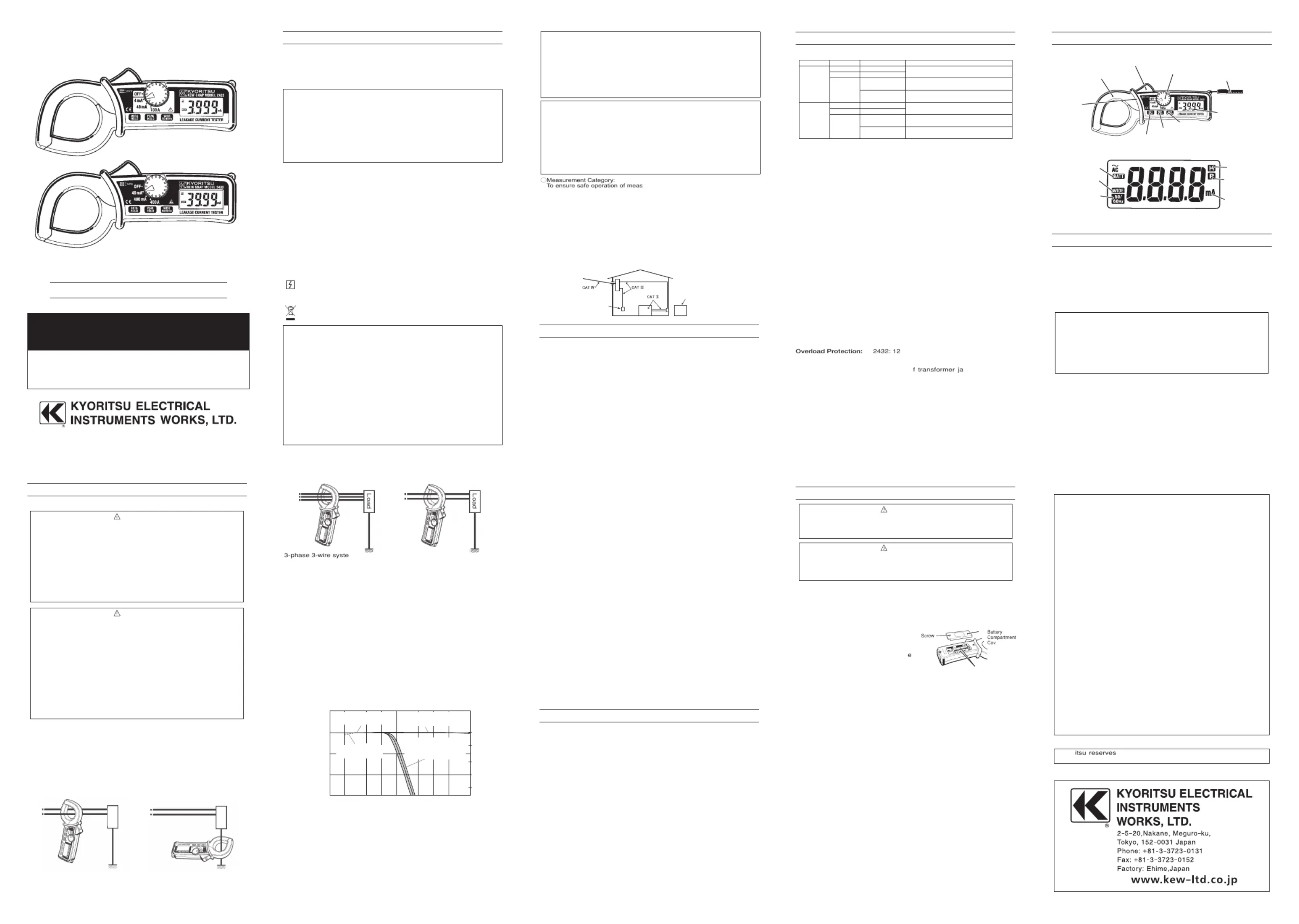
4. INSTRUMENT LAYOUT
5. PREPARATIONS FOR MEASUREMENT
5-1 Checking Battery Voltage
Set the Range Selector Switch to any position other than the OFF
position. If the marks on the display is clearly visible without "BATT"
mark showing, battery voltage is OK. If the display blanks or "BATT"
is indicated, replace the batteries according to section 8: Battery
Replacement.
NOTE
When the instrument is left powered on, the auto-power-off
function automatically shut the power off; The display blanks even
if the Range Selector Switch is set to a position other than the
OFF position in this state. To power on the instrument, turn the
Range Selector Switch or press the Data Hold Button. If the
display still blanks, the batteries are completely exhausted.
Replace the batteries.
5-2 Checking Switch Setting
Make sure that the Range Selector Switch is set to the appropriate
range.
Also make sure that data hold function is not enabled. If
inappropriate range is selected, desired measurement cannot be
made.
Transform Jaws
Barrier
Trigger
Range Selector Switch
Hand Strap
Display
Frequency Selector Button
Peak Hold Button
Data Hold Button
●LCD
Low Battery Warning
Frequency Response :
Wide
Frequency Response :
50/60Hz
Data Hold Indication
Peak Hold Indication
Function
6. OPERATING INSTRUCTIONS
6-1 Current Measurement
DANGER
●tIn order to avoid possible shock hazard, never make measuremen
on circuits having a potential of 300VAC or greater.
●The transformer jaws are made of metal and their tips are not
completely insulated. Be especially careful about the possible
shorting where the equipment under test has exposed metal parts.
●Never make measurement with the battery compartment cover
removed.
●When measuring current is 300A or more ( 400Hz or more ), be sure to
stop measurement within 5 minutes. Otherwise, transformer jaws may
heat to cause a fire or deformation of molded parts, which willdegrade
insulation.
●Keep your fingers and hands behind the barrier during measurement.
CAUTION
●Take sufficient care to not to apply shock, vibration or
excessive force to the jaw tips. Otherwise, precisely adjusted
Transformer Jaw tips will be damaged.
●When a foreign substance is stuck in the jaw tips or they
cannot properly engage, the transformer jaws do not fully
close. In such a case, do not release the jaw trigger abruptly or
attempt to close the transformer jaws by applying external
force. Make sure that the jaws close by themselves after
removing the foreign substance or making them free to move.
●The maximum size of a conductor to be tested is 40mm in
diameter. Accurate measurement cannot be made on a
conductor larger than this, because the transformer jaws
cannot fully close.
●When measuring large current, the transformer jaws may buzz.
This has no effect on the instrument's performance or safety.
(1)Set the Range Selector Switch to the desired position. Current
to measure should be within the selected measuring range.
(2)Normal measurement (See Fig.1, 2):
Press the jaw trigger to open the transformer jaws and close
them over one conductor only. Measured current value is shown
on the display. Earth leakage current or small current that flows
through a grounded wire can also be measured by this method.
(3)Measuring out of balance leakage current (See Fig. 3):
Clamp onto all conductors except a grounded wire. Measured
current value is shown on the display.
Fig. 1 Load currentFig. 2 Earth leakage current
Load
Load
Note:
Characteristic of -24dB/octiave means that signal magnitude
declines to about one sixteenth of that at the initial frequency when
frequency doubles. KEW SNAP 2432 and KEW SNAP 2433 have
the following two settings for the Frequency Selector Button.
WIDE (20Hz-): Permits measurement of currents of fundamental
frequencies as well as currents of high frequencies
generated by such equipment as inverters
50/60Hz (20-approx.160Hz): Filters out high frequency currents and
measures current of fundamental
frequency only
Fig. 3 Measuring out of balance leakage current
Fig.4 KEW SNAP 2432/2433 Frequency Characteristic
Output characteristic are shown in Fig.4.
Load
Load
3-phase 3-wire system
(In 4-wire system with neutral,
clamp onto all 4 wires)
Single-phase 2-wire system
(in 3-wire system with neutral,
clamp onto all 3 wires)
Recently there has been increased use of power through inverters,
switching regulators, etc. When the high frequency noise from such
appliances leaks or flows into the ground through capacitors not
filtering completely, the earth leakage breaker may trip even though
there is no "actual" leakage. In such a case, the instrument do not
give leakage current reading if "50/60Hz" frequency response is
selected.
Take current readings with the 50/60Hz and WIDE frequency
responses respectively to make effective use of the Frequency
Selector Button.
6-3 Peak Current Measurement
(1)Set the Range Selector Switch to the desired position.(Current to
measure should not exceed the selected measuring range.)
(2)Select "WIDE"or "50/60Hz"with the Frequency Selector Button.
(3)With the transformer jaws clamped onto the conductor under
test, press the Peak Hold Button to set the interment to the peak
measurement mode.("P" is shown on the display.)
(4)The display reads 1/√2 of the peak current value. Therefore,an
rms reading is shown when current of a sinusoidal waveform is
measured.
(5)After peak measurement, press the Peak Hold Button to return to
the normal measurement mode.
Note: When leakage current is measured in the peak measurement
mode, the reading may change if the transformer jaws are
opened and closed. Please read the display with the conductor
under test clamped, otherwise, after fixing the display by using
the data hold function, please remove the instrument from the
conductor to be measured, and read the display. To measure
the peak current again, please release the data hold, and return
the instrument to the normal measurement mode once with the
Peak Hold Button, then set it in the peak measurement mode.
7. OTHER FUNCTIONS
7-1 Auto-Power-Off Function
This is a function to prevent the instrument from being left powered
on and conserve battery power. The instrument automatically turns
off about 10 minutes after the last switch or button operation. To
return to the normal mode, turn the Range Selector Switch to OFF,
then to the desired position.
Disabling Auto-Power-Off Function:
To disable the auto-power-off function, power on the instrument
with the Data Hold Button pressed. About 3 seconds after powering
on the instrument, "P.OFF" is shown on the display. To enable the
auto-power-off function, turn on the instrument without pressing the
Data Hold Button.
Note: The auto-power-off function is disabled in the peak
measurement mode.
7-2 Date Hold Function
This is a function to freeze the readings on the display. When the
Data Hold Button is pressed once, the current reading is held even
though current under test varies. "H" mark is shown on the upper
right corner of the display.
To exit the data hold mode, press the Data Hold Button again.
Note: When the auto-power-off function works while the instrument
is in the data hold mode, data hold is cancelled.
8. BATTERY REPLACEMENT
WARNING
In order to avoid possible shock hazard, always set the Range
Selector Switch to the OFF position before trying to replace the
batteries.
CAUTION
●Do not mix new and old batteries.
●Install batteries in the orientation as shown inside the battery
compartment, observing correct polarity.
When the battery voltage warning mark "BATT" is shown on the
top left corner of the LCD, replace the batteries. Note that the
display blanks and "BATT" mark is not shown if the batteries are
completely exhausted.
(1)Set the Range Selector Switch to "OFF."
(2)Loosen the battery-compartment-
cover-fixing screw on the lower
back of the instrument.
(3)Replace the batteries with two
new R03 (UM-4) 1.5V batteries.
(4)Put the battery compartment
cover back in place and tighten
the screw.
Note: For use for a long period of time,
use alkaline batteries.
Screw
Battery
Compartment
Cover
Batteries
DISTRIBUTOR
Kyoritsu reserves the rights to change specifications or designs
described in this manual without notice and without obligations.
Overload Protection:2432: 120AAC max. for 10 seconds
2433: 480AAC max. for 10 seconds
Withstand Voltage:VACrms (50/60Hz) for
metal part of transformer jaws and housing
case (except transformer jaw case)
Insulation Resistance:10MΩor greater at 1000V between metal
part of transformer jaws and housing case
(except transformer jaw case)
Conductor Size:Approx. 40mm in diameter max.
Dimensions:185(L)×81(W)×32(D)mm
Weight:2432: Approx. 290g including batteries
2433: Approx. 270g including batteries
Accessories:Two R03 (UM-4) batteries
Carrying case Model 9052
Instruction manual
○Measurement Category:
To ensure safe operation of measuring instruments, IEC 61010 establishes
safety standards for various electrical environments, categorized as O to
CAT IV, and called measurement categories. Higher-numbered categories
correspond to electrical environments with greater momentary energy, so a
measuring instrument designed for CAT III environments can endure
greater momentary energy than one designed for CAT II.
O :
Circuits which are not directly connected to the mains power supply.
CAT II : Electrical circuits of equipment connected to an AC electrical outlet
by a power cord.
CAT III :
Primary electrical circuits of the equipment connected directly to the
distribution panel, and feeders from the distribution panel to outlets.
CAT IV : The circuit from the service drop to the service entrance, and to the
power meter and primary over-current protection device
(distribution panel).
Incoming wire
O:
Device which is
not directly
connected to the
mains power supply
Socket
Interior wiring
3470
5 sec. between
92
-
1452
L
4
-
22
1. SAFETY WARNINGS
ThisinstrumenthasbeendesignedandtestedaccordingtoIEC
Publication61010:SafetyRequirementsforElectronicMeasuring
Apparatus.Thisinstructionmanualcontainswarningsandsafety
ruleswhichmustbeobservedbytheusertoensuresafeoperation
oftheinstrumentandtoretainitinsafecondition.Therefore,
readthroughtheseoperatinginstructionsbeforestartingusingthe
instrument.
#
WARNING
●Readthroughandunderstandinstructionscontainedinthis
manualbeforestartingusingtheinstrument.
●Saveandkeepthemanualhandytoenablequickreference
whenevernecessary.
●Theinstrumentistobeusedonlyinitsintendedapplications.
●Understandandfollowallthesafetyinstructionscontainedinthe
manual.
Failuretofollowtheinstructionsmaycauseinjury,instrument
damageand/ordamagetoequipmentundertest.Kyoritsuisbyno
meansliableforanydamageresultingfromtheinstrumentin
contradictiontothiscautionarynote.
Thesymbol
#
indicatedontheinstrumentmeansthattheusermust
refertorelatedpartsofthemanualforsafeoperationofthe
instrument.Besuretocarefullyreadtheinstructionsfollowingeach
#
symbolinthismanual.
#
DANGER isreservedforconditionsandactionsthatarelikely
tocauseseriousorfatalinjury.
#
isreservedforconditionsandactionsthatcancauseWARNING
seriousorfatalInjury.
#
isreservedforconditionsandactionsthatcancauseCAUTION
minorinjuryorInstrumentdamage.
Followingsymbolsareusedontheinstrumentandintheinstruction
manual.Attentionshouldbepaidtoeachsymboltoensureyoursafety.
#
Refertotheinstructionsinthemanual.
Thissymbolismarkedwheretheusermustrefertothe
instructionmanualsoasnottocausepersonalinjuryor
instrumentdamage.
Indicatesaninstrumentwithdoubleorreinforcedinsulation.
Indicatesthatthisinstrumentcanclamponbareconductors
whenmeasuringavoltagecorrespondingtotheapplicable
Measurementcategory,whichismarkednexttothissymbol.
IndicatesAC(AlternatingCurrent).
Thisinstrumentsatisfiesthemarkingrequirementdefinedin
theWEEEDirective(2002/96/EC).Thissymbolindicates
separatecollectionforelectricalandelectronicequipment.
#
DANGER
●Nevermakemeasurementonacircuithavingpotentialof
300VACorgreater.
●Donotattempttomakemeasurementinthepresenceof
flammablegasses.Otherwise,theuseoftheinstrumentmay
causesparking,whichleadstoanexplosion.
●Thetransformerjawsaremadeofmetalandtheirtipsarenot
completelyinsulated.Beespeciallycarefulaboutthepossible
shortingwheretheequipmentundertesthasexposedmetalparts.
●Neverattempttousetheinstrumentifitssurfaceoryourhandiswet.
●
Donotexceedthemaximumallowableinputofanymeasurementrange.
●Neveropenthebatterycompartmentcoverwhenmaking
measurement.
●Nevertrytomakemeasurementifanyabnormalconditions,such
asbrokenTransformerjawsorcaseisnoted.
●Theinstrumentistobeusedonlyinitsintendedapplicationsor
conditions.Otherwise,safetyfunctionsequippedwiththe
instrumentdoesn'twork,andinstrumentdamageorserious
personalinjurymaybecaused.
●
Keepyourfingersandhandsbehindthebarrierduringmeasurement.
#
WARNING
●Neverattempttomakeanymeasurement,ifanyabnormal
conditionsarenoted,suchasbrokencase,crackedtestleads
andexposedmetalparts.
●Donotinstallsubstitutepartsormakeanymodificationtothe
instrument.ReturntheinstrumenttoKyoritsuoryourdistributor
forrepairorre-calibration.
●Donottrytoreplacethebatteriesifthesurfaceoftheinstrument
iswet.
●Alwaysswitchofftheinstrumentbeforeopeningthebattery
compartmentcoverforbatteryreplacement.
#
CAUTION
●Makesurethattherangeselectorswitchissettoanappropriate
positionbeforemakingmeasurement.
●Donotexposetheinstrumenttothedirectsun,extreme
temperaturesordewfall.
●Besuretosettherangeselectorswitchtothe"OFF"position
afteruse.Whentheinstrumentwillnotbeinuseforalong
periodoftime,placeitinstorageafterremovingthebatteries.
●Useadampclothanddetergentforcleaningtheinstrument.Do
notuseabrasivesorsolvents.
●
Thisinstrumentisn'tdust&waterproofed.Keepawayfromdust
andwater.
MeasurementCAT300V,pollutiondegree2Ⅲ
IEC61326-1(EMC)
6-2HowtoUseFrequencySelectorButton
Whenhighfrequenciesfromsuchequipmentasinvertersare
presentinthecircuitundertest,theinstrumentmeasuresAC
currentofnotonly50Hzor60Hzoffundamentalfrequencybut
alsoofthesehighfrequenciesandharmonics.
Toeliminatetheeffectofsuchhighfrequencynoiseandmeasure
ACcurrentof50Hzor60Hzfundamentalfrequency,a"Low
pass"filtercircuitinincorporatedintotheinstrumentwhichworks
when"50/60Hz"frequencyresponseisselectedwiththe
FrequencySelectorButton.Cut-offfrequencyofthe"Lowpass"
filterisabout160Hzwithattenuationcharacteristicofapprox.
-24dB/octave.
WhentheFrequencySelectorButtonispressed,"50/60Hz"mark
isshownontheleftsideofthedisplay.WhentheFrequency
SelectorButtonispressedagain,fequencyresponseisswitched
toWIDEwith"WIDE"markshownonthedisplay.
100%
50%
20%
10%
5%
5k1k2k500100200502010
ー30
ー20
ー10
0
Attenuation〔dB〕
10
Frequency〔Hz〕
Percentage
Typical characteristic:
4/40/400mA Range
Typical characteristic:
“WIDE”frequency response
Typical characteristic:
“50/60Hz”frequency response
Low pass filter -24dB/oct
Typical characteristic:
100/400A Range
Environmental standards:
EURoHSdirectivecompliant
Product specificaties
| Merk: | Kyoritsu |
| Categorie: | Multimeter |
| Model: | KEW Snap 2433 |
Heb je hulp nodig?
Als je hulp nodig hebt met Kyoritsu KEW Snap 2433 stel dan hieronder een vraag en andere gebruikers zullen je antwoorden
Handleiding Multimeter Kyoritsu

1 December 2024
1 December 2024
1 December 2024
5 Januari 2024
5 Januari 2024
5 Januari 2024
5 Januari 2024
5 Januari 2024
4 Januari 2024
4 Januari 2024
Handleiding Multimeter
Nieuwste handleidingen voor Multimeter
12 Juli 2026
12 Juli 2026
12 Juli 2026
8 Juli 2026
2 Juni 2026
18 Mei 2026
6 Mei 2026
6 Mei 2026
21 April 2026
21 April 2026