Kyoritsu 2431 Handleiding
Kyoritsu Multimeter 2431
Bekijk gratis de handleiding van Kyoritsu 2431 (2 pagina’s), behorend tot de categorie Multimeter. Deze gids werd als nuttig beoordeeld door 128 mensen en kreeg gemiddeld 4.3 sterren uit 2 reviews. Heb je een vraag over Kyoritsu 2431 of wil je andere gebruikers van dit product iets vragen? Stel een vraag
Pagina 1/2
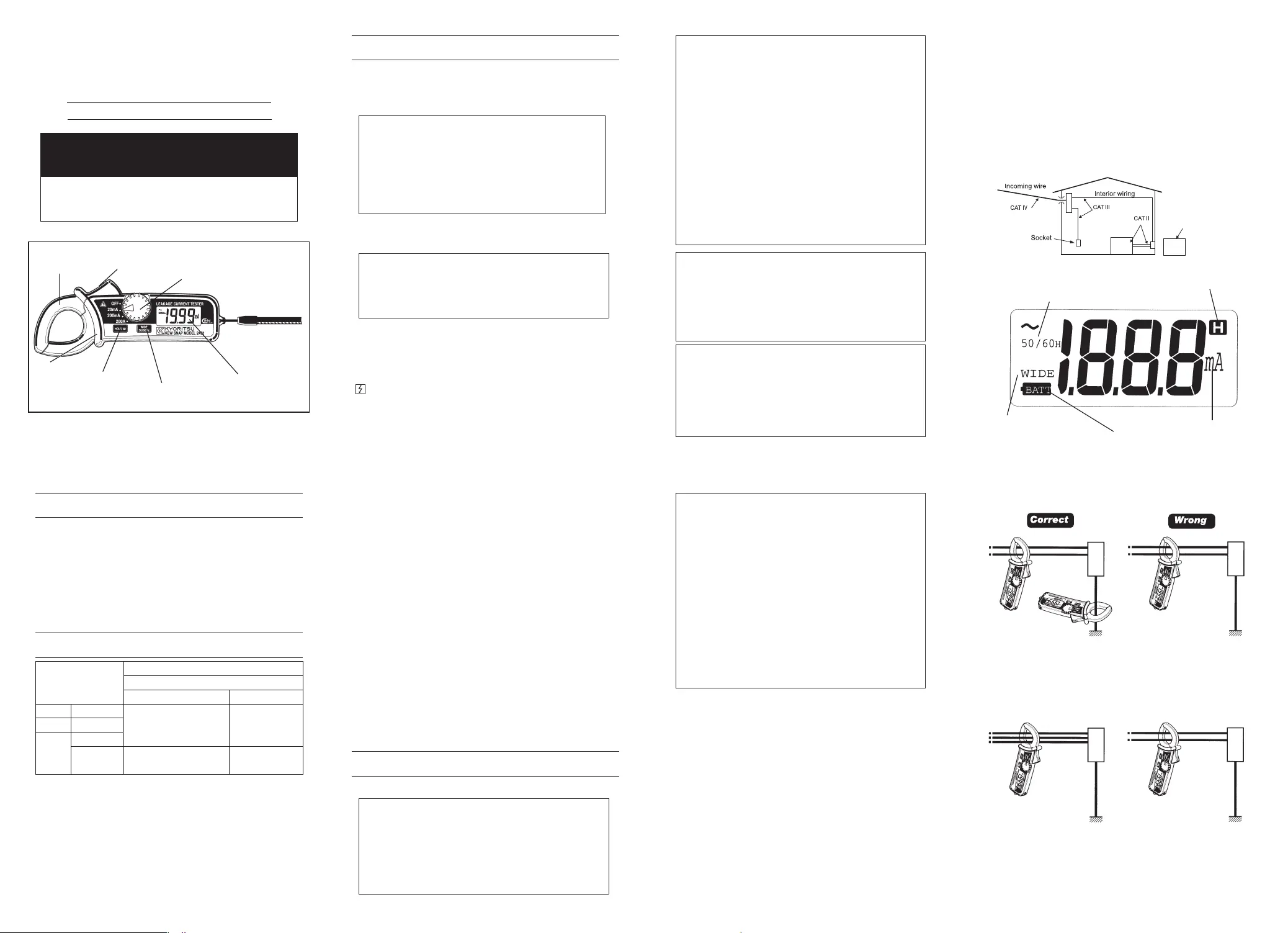
Jaw Trigger
Range Switch
Data Hold Button
Transformer Jaws
Display
Frequency Selector Switch
INSTRUMENT LAYOUT
Barrier
INSTRUCTION MANUAL
DIGITAL AC LEAKAGE CLAMP METER
KEW SNAP 2431
KEW SNAP
SERIES
1.SAFETY WARNINGS
This instrument has been designed and tested according to IEC
Publication 61010; Safety Requirements for Electronic Measuring
Apparatus.This instruction manual contains warnings and safety rules
which must be observed by the user to ensure safe operation of the
instrument and retain it in safe condition. Therefore, read through these
operating instructions before using the instrument.
#
WARNING
WARNING
* Read through and understand instructions contained in this
manual before starting using the instrument.
* Save and keep the manual handy to enable quick reference
whenever necessary.
* The instrument is to be used only in its intended applications.
* Understand and follow all the safety instructions contained in
the manual.
Failure to follow the instructions may cause injury, instrument
damage and/or damage to equipment under test. Kyoritsu is by
no means liable for any damage resulting from the instrument
in contradiction to this cautionary note.
The symbol
#
indicated on the instrument means that the user must
refer to related parts in the manual for safe operation of the instrument.
Be sure to carefully read instructions following each
#
symbol in this
manual.
#
DANGER
DANGERis reserved for conditions and actions that are
likely to cause serious or fatal injury.
#
WARNING
WARNINGis reserved for conditions and actions that can
cause serious or fatal injury.
#
CAUTION
CAUTION
is reserved for conditions and actions that can
cause injury or property damage.
Following symbols are used on the instrument and in the instruction
manual. Attention should be paid to each symbol to ensure your safety.
#
Refer to the instructions in the manual.
This symbol is marked where the user must refer to the instruction
manual
so as not to cause personal injury or instrument damage.
Indicates an instrument with double or reinforced insulation.
Indicates that this instrument can clamp on bare conductors when
measuring a voltage corresponding to the applicable Measurement
category, which is marked next to this symbol.
Indicates AC (Alternating Current).
#
DANGER
DANGER
* Never make measurement on a circuit above 300V AC. The
instrument is designed for measurement on a low-voltage circuit
below 300V AC.
* Do not attempt to make measurement in an explosive
atmosphere
(
i.e. in the presence of flammable gasses or fumes,
vapor or dust
)
.
* The transformer jaws are made of metal and their tips are not
insulated. Be especially careful about the hazard of possible
shorting where equipment under test has exposed conductive
parts.
* Never attempt to use the instrument if the instrument or your
hand is wet.
* Do not exceed the maximum allowable input value of any
measurement range.
* Never open the battery compartment cover when making
measurement.
* Never try to make measurement if any abnormal conditions,
such as broken Transformer jaws or case is noted.
* The instrument is to be used only in its intended applications or
conditions. Otherwise, safety functions equipped with the
instrument doesn’t work, and instrument damage or serious
personal injury may be caused.
*
Keep your fingers and hands behind the barrier during
measurement.
#
WARNING
WARNING
* Never attempt to make any measurement if the instrument has
any structural abnormality such as cracked case and exposed
metal part.
* Do not install substitute parts or make any modification to the
instrument. Return the instrument to Kyoritsu or your distributor
for service and repair to ensure that safety features are
maintained.
* Always switch off the instrument before opening the battery
compartment cover for battery replacement.
#
CAUTION
CAUTION
* Make sure that the range switch is set to an appropriate
position before making measurement.
* Be sure to set the range switch to the OFF position after use.
When the instrument will not be in use for a long period of
time, place it in storage after removing the batteries.
* Do not expose the instrument to the direct sun, extreme
temperatures or dew fall.
*
Use a damp cloth and detergent for cleaning the instrument.
Do not use abrasives or solvents.
Measurement categories (Over-voltage categories)
To ensure safe operation of measuring instruments, IEC 61010
establishes safety standards for various electrical environments,
categorized as O to CAT IV, and called measurement categories.
Higher-numbered categories correspond to electrical environments with
greater momentary energy, so a measuring instrument designed for CAT
III environments can endure greater momentary energy than one
designed for CAT II.
O : Circuits which are not directly connected to the mains power
supply.
CAT II : Primary electrical circuits of equipment connected to an AC
electrical outlet by a power cord.
CAT III : Primary electrical circuits of the equipment connected directly
to the distribution panel, and feeders from the distribution
panel to outlets.
CAT IV : The circuit from the service drop to the service entrance, and
to the power meter and primary overcurrent protection device
(distribution panel).
O: Device which is
not directly
connected to the
mains power supply
Data Hold mode indicator
Unit of measured quantity
Low battery indicator
Frequency response of 50/60Hz
Frequency response of WIDE
2.FEATURES
* Digital clamp meter designed for measurement of AC leakage current.
* Tear-drop-shaped jaws for ease of use in crowded cable areas and
other tight places
* Data hold function to allow for easy readings in dimly light or hard-to-
read locations
* Filter function to remove harmonics generated by such equipment as
inverters
* Automatic power-off function to extend battery life
* Designed to CAT Ⅲ 300V and pollution degree2 specified by the
international safety standard,IEC 61010-1.
3.SPECIFICATIONS
Ranges
Accuracy
Frequency Selector Switch
WIDE position50/60 position
20mA0〜19.99mA
±2.0%rdg±4dgt(50/60Hz)
±5.0%rdg±6dgt(40〜400Hz)
±3.0%rdg±5dgt
(50/60Hz)
200mA0〜199.9mA
200A
0〜100.0A
100.1〜
199.9A
±5.0%rdg±4dgt(50/60Hz)
±5.0%rdg±5dgt
(50/60Hz)
Overrange Indication :'1' flashes on the highest digit
Response Time :Approx. 2 seconds
Sample Rate :Twice per second
Location for us :
Indoor use, Altitude up to 2000m
Data Hold :For all ranges
Storage Temperature & Humidity : −10-50℃, relative humidity up
to 75%(without condensation)
Operating Temperature & Humidity: 0-40℃, relative humidity up to
85%(without condensation)
Power Source :Two LR-44 or SR-44 batteries
Current Consumption :Approx. 5mA
Battery Life : Approx. 15 hours in continuous
use
Auto Power Off : Automatically turns off approx.
10 minutes after power-on.
Safety Standards : IEC 61010-1 CAT III 300V
Pollution degree 2
:IEC 61010-2-32
EMC Standards :IEC 61326-1
Environmental standards :EU RoHS Directive compliant
Overload :AC300A for one minute
Withstand Voltage : 3470V AC for 5 seconds
between electrical circuit and
housing case
Conductor Size :Approx. 24mm in diameter
Dimensions :149(L)×60(W)×26(D)mm
Weight :Approx.120g(battery included)
Accessories : Instruction Manual, Two LR-44
batteries Carrying Case
4.OPERATlNG INSTRUCTIONS
4
−
1
AC Current Measurement
AC Current Measurement
#
DANGER
DANGER
* Never use the instrument on a circuit above 300V AC.
* The transformer jaws are made of metal and their tips are not
insulated. Be especially careful about the hazard of possible
shorting where equipment under test has exposed conductive
parts.
* Do not attempt to make measurement with the battery
compartment cover removed from the instrument.
* Keep your fingers and hands behind the barrier during
measurement.
Barrier: It is a part providing protection against electrical shock and
ensuring the minimum required air and creepage distances.
#
CAUTION
CAUTION
* The transformer jaws, especially their tips, have been precisely
adjusted to obtain maximum accuracy. Take sufficient care to
avoid shock, vibration or excessive force when handling the
instrument.
* The transformer jaws do not fully close when a foreign
substance is stuck in the jaw tips or they do not properly engage
due to the excessive force applied. In such a case do not
release the jaw trigger suddenly or attempt to close the
transformer jaws by applying external force. Make sure that the
jaws close by themselves after removing the foreign substance
or making them free to move.
* The maximum size of a conductor to test is approx. 24 mm in
diameter. An accurate measurement cannot be made when the
transformer jaws are not fully closed on a conductor larger than
24mm.
* When measuring a large current, the transformer jaws may
buzz. This is not a fault nor affect the accuracy of the instrument.
(1) Set the range switch to a desired range. (Make sure that current to
measure does not exceed the upper limit of the range.)
(2) For normal measurement(Fig.1), press the jaw trigger to open the
transformer jaws and clamp onto one conductor only. Earth leakage
current and small current that flow through a grounded wire can also
be measured by this method. It is recommended that the conductor
is placed at the center of the closed transformer jaws.
(3) To measure out of balance leakage current(Fig.2), clamp onto all
conductors except a grounded wire. The leakage current measured
will be indicated on the display.
In a 4-wire system, clamp onto
all 4 wires.
In a 3-wire system, clamp onto all
3 wires.
Three-phase, 3-wire systems
Single-phase, 2-wire systems
Fig. 1 Normal Measurement
Fig.2 Out-of-balance Leakage Current Measurement
Product specificaties
| Merk: | Kyoritsu |
| Categorie: | Multimeter |
| Model: | 2431 |
Heb je hulp nodig?
Als je hulp nodig hebt met Kyoritsu 2431 stel dan hieronder een vraag en andere gebruikers zullen je antwoorden
Handleiding Multimeter Kyoritsu

1 December 2024
1 December 2024
1 December 2024
5 Januari 2024
5 Januari 2024
5 Januari 2024
5 Januari 2024
5 Januari 2024
4 Januari 2024
4 Januari 2024
Handleiding Multimeter
Nieuwste handleidingen voor Multimeter
12 Juli 2026
12 Juli 2026
12 Juli 2026
8 Juli 2026
2 Juni 2026
18 Mei 2026
6 Mei 2026
6 Mei 2026
21 April 2026
21 April 2026