Kyoritsu 2434 Handleiding
Kyoritsu Multimeter 2434
Bekijk gratis de handleiding van Kyoritsu 2434 (2 pagina’s), behorend tot de categorie Multimeter. Deze gids werd als nuttig beoordeeld door 52 mensen en kreeg gemiddeld 4.4 sterren uit 9 reviews. Heb je een vraag over Kyoritsu 2434 of wil je andere gebruikers van dit product iets vragen? Stel een vraag
Pagina 1/2
INSTRUCTIONMANUAL
KEW SNAP
2434
KEW SNAPSeries
LEAKAGECURRENTTESTER
KYORITSU ELECTRICAL INSTRUMENTS WORKS, LTD.,
TOKYO, JAPAN
1. SAFETY WARNINGS
ThisinstrumenthasbeendesignedandtestedaccordingtoIEC
Publication61010:SafetyRequirementsforElectronicMeasuring
Apparatus.Thisinstructionmanualcontainswarningsandsafetyrules
whichmustbeobservedbytheusertoensuresafeoperationofthe
instrumentandtoretainitinsafecondition.Therefore,readthroughthese
operatinginstructionsbeforestartingusingtheinstrument.
#
WARNING
●
Readthroughandunderstandinstructionscontainedinthismanual
beforestartingusingtheinstrument.
●
Saveandkeepthemanualathandtoenablequickreferencewhenever
necessary.
●
Besuretousetheinstrumentonlyinitsintendedapplicationsandto
followmeasurementproceduresdescribedinthemanual.
●
Besuretounderstandandfollowallsafetyinstructionscontainedin
themanual.
Notfollowingtheaboveinstructionsmaycauseinjury,instrumentdamage
and/ordamagetoequipmentundertest.
Theinstrumentistobeusedonlyinitsintendedapplications.
Understandandfollowallthesafetyinstructionscontainedinthemanual.
Failuretofollowtheinstructionsmaycauseinjury,instrumentdamageand/
ordamagetoequipmentundertest.Kyoritsuisbynomeansliableforany
damageresultingfromtheinstrumentincontradictiontothiscautionarynote.
Thesymbol
#
indicatedontheinstrumentmeansthattheusermustrefer
torelatedpartsofthemanualforsafeoperationoftheinstrument.Besure
tocarefullyreadtheinstructionsfollowingeach
#
symbolinthismanual.
#
DANGER
isreservedforconditionsandactionsthatarelikelyto
causeseriousorfatalinjury.
#
WARNING
isreservedforconditionsandactionsthatcancause
seriousorfatalInjury.
#
CAUTION
isreservedforconditionsandactionsthatcancause
minorinjuryorInstrumentdamage.
Followingsymbolsareusedontheinstrumentandintheinstruction
manual.Attentionshouldbepaidtoeachsymboltoensureyoursafety.
#
Refertotheinstructionsinthemanual.
Indicatesaninstrumentwithdoubleorreinforcedinsulation.
Indicatesthatthisinstrumentcanclamponbareconductorswhen
measuringavoltagecorrespondingtotheapplicableMeasurement
category,whichismarkednexttothissymbol.
IndicatesAC(AlternatingCurrent).
IndicatesEarth.
#
DANGER
●
Nevermakemeasurementonacircuithavingpotentialof300VACor
greater.
●
Donotattempttomakemeasurementinthepresenceofflammable
gasses.Otherwise,theuseoftheinstrumentmaycausesparking,
whichleadstoanexplosion.
●
Thetransformerjawsaremadeofmetalandtheirtipsarenot
completelyinsulated.Beespeciallycarefulaboutthepossibleshorting
wheretheequipmentundertesthasexposedmetalparts.
●
Neverattempttousetheinstrumentifitssurfaceoryourhandiswet.
●
Donotexceedthemaximumallowableinputofanymeasurementrange.
●
Neveropenthebatterycompartmentcoverwhenmakingmeasurement.
●
Nevertrytomakemeasurementifanyabnormalconditions,suchas
brokenTransformerjawsorcaseisnoted.
●
Theinstrumentistobeusedonlyinitsintendedapplicationsorconditions.
Otherwise,safetyfunctionsequippedwiththeinstrumentdoesn'twork,and
instrumentdamageorseriouspersonalinjurymaybecaused.
●
Keepyourfingersandhandsbehindthebarrierduringameasurement.
#
WARNING
●
Neverattempttomakeanymeasurement,ifanyabnormalconditions
arenoted,suchasbrokencase,crackedtestleadsandexposedmetal
parts.
●
Donotinstallsubstitutepartsormakeanymodificationtothe
instrument.ReturntheinstrumenttoKyoritsuoryourdistributorfor
repairorre-calibration.
#
CAUTION
●
Makesurethattherangeselectorswitchissettoanappropriate
positionbeforemakingmeasurement.
●
Donotexposetheinstrumenttothedirectsun,extremetemperatures
ordewfall.
●
Besuretosettherangeselectorswitchtothe"OFF"positionafter
use.Whentheinstrumentwillnotbeinuseforalongperiodoftime,
placeitinstorageafterremovingthebatteries.
●
Useadampclothanddetergentforcleaningtheinstrument.Donot
useabrasivesorsolvents.
●
Alwaysswitchofftheinstrumentbeforeopeningthebattery
compartmentcoverforbatteryreplacement.
Measurementcategories(Over-voltagecategories)
Toensuresafeoperationofmeasuringinstruments,IEC61010establishessafety
standardsforvariouselectricalenvironments,categorizedasOtoCATIV,and
calledmeasurementcategories.
Higher-numberedcategoriescorrespondtoelectricalenvironmentswithgreater
momentaryenergy,soameasuringinstrumentdesignedforCATIIIenvironments
canenduregreatermomentaryenergythanonedesignedforCATII.
O:Circuitswhicharenotdirectlyconnectedtothemainspowersupply.
CATII:PrimaryelectricalcircuitsofequipmentconnectedtoanACelectrical
outletbyapowercord.
CATIII:Primaryelectricalcircuitsoftheequipmentconnecteddirectlytothe
distributionpanel,andfeedersfromthedistributionpaneltooutlets.
CATIV:Thecircuitfromtheservicedroptotheserviceentrance,andtothe
powermeterandprimaryovercurrentprotectiondevice(distribution
panel).
2. FEATURES
●
DigitalclamptesterforACleakagecurrentmeasurement.
●
Leastaffectedbyexternalmagneticfield,providingwidemeasuring
rangefromverysmalltolargecurrents.
●
DesignedtosafetystandardIEC61010-2-032:measurementCAT.
Ⅲ
,
300Vandpollutiondegree2.
●
Dataholdfunctiontoallowforeasyreadingsindimlylitorhard-to-
reachlocations.
●
Providesfilteringfunctiontoremovehighfrequencygeneratedbysuch
equipmentasinverters.
●
Sleepfunctionpreventsunnecessarypowerconsumption.
●
Dynamicrangeof4000countsfullscale.
●
Largeeasy-to-readLCDdisplaywithletterheightof13mm.
●
Transformerjawsfittedwithguardtofurtherimprovesafety.
O: Device which is
not directly
connected to the
mains power supply
3. SPECIFICATIONS
Measuringrangesandaccuracy
RangeMeasuringRangeAccuracy(Frequencyrange)
400mA0
〜
399.9mA
±
2.0%rdg
±
4dgt
(
50/60Hz
)
±
3.0%rdg
±
5dgt
(
40
〜
400Hz
)
4A0
〜
3.999A
100A0
〜
100.0A
Whenmeasuringcurrentwhichpulseelementissuperposed,differencesofthe
indicatedvaluemaybecausedbetweenranges,ifthepeakvalueexceedsthe
measurementrangetoalargeextent.Inthiscase,thereadingatthebigger
rangeshouldbetakenasarightvalue.
SensitivetransformerjawsareusedforLeakageclampmeter.Becauseofthe
characteristicsoftransformerjaws,whichcanbeopenedandclosed,itis
impossibletoeliminatetheinterferenceofexternalmagneticfieldcompletely.If
therearesomething,whichgeneratinglargemagneticfield,atanearbysite,
currentvaluecanbedisplayed(
0
cannotbedisplayed.)beforeclampingon
theconductor.Forsuchacase,pleaseusetheinstrumentatalocationfarfrom
thething,whichgeneratingmagneticfield.
Followingarethetypicalthingsgeneratingmagneticfield.
Conductorfedlargecurrent,Motor,Equipmentwhichhasmagnet,Integrating
wattmeter
Measuring method:
DualIntegration
Display:
Liquidcrystaldisplaywithmaximumreadingof
3999
Low battery warning:
"BATT"markappearsonthedisplay
Overrange Indication:
"OL"appearsonthedisplaywhenupperlimitof
measuringrangeisexceeded
Response Time:
Approx.2seconds
Sample Rate:
Approx.2.5timespersecond
Location for use
Indooruse,Altitudeupto2000m
Accuracy-insured
23
℃±
5
℃
,relativehumidity85%orless
Temperature and
(withoutcondensation)
Humidity Ranges:
Operating Temperature
0-40
℃
,relativehumidity85%orless
and Humidity Ranges:
(withoutcondensation)
Storage Temperature
-20-60
℃
,relativehumidity85%orless
and Humidity Ranges:
(withoutcondensation)
Power Source:
Two1.5VR03(UM-4)batteries
Current Consumption:
Approx.4mA
Measurement Time:
Approx.150hours
Sleep Function:
Automaticallypowereddowninabout10
minutesafterthelastswitchoperation
Safety Standard:
IEC61010-1,IEC61010-2-032
measurementCAT.
Ⅲ
300V,pollutiondegree2
IEC61326(EMC),EN50581(RoHS)
Overload Protection:
120Armsmax.for10seconds
Withstand Voltage:
3470Vrms(50/60Hz)for5secondsbetween
metalpartoftransformerjawsandhousingcase
(excepttransformerjawcase)
Insulation Resistance:
10M
Ω
orgreaterat1000Vbetweenmetalpart
oftransformerjawsandhousingcase(except
transformerjawcase)
Conductor Size:
Approx.28mmindiametermax.
Dimensions:
169(L)
×
75(W)
×
40(D)mm
Weight:
Approx.220gincludingbatteries
Accessories:
TwoR03(UM-4)batteries
CarryingcaseModel9097
Instructionmanual
Optional Accessories:
Multi-TranModel8008
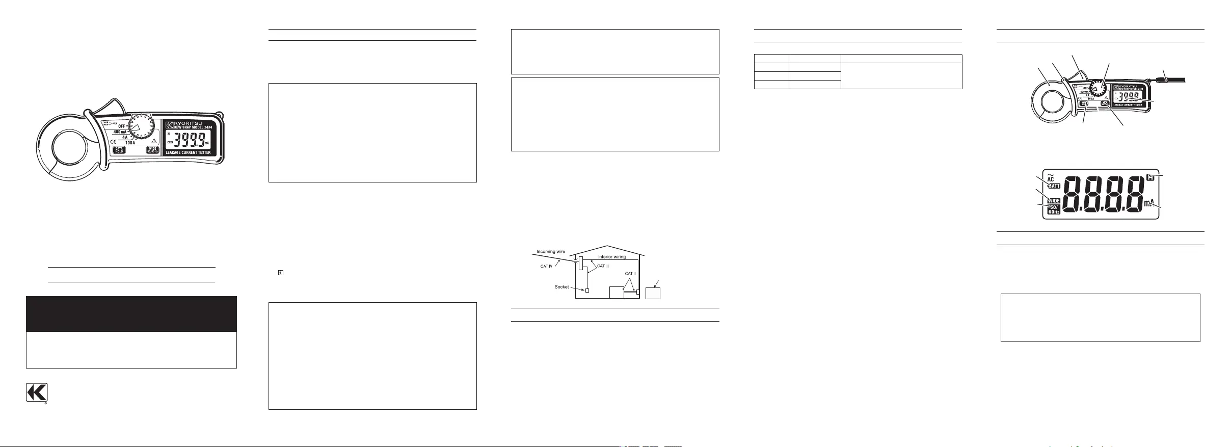
4. INSTRUMENT LAYOUT
5. PREPARATIONS FOR MEASUREMENT
5-1 Checking Battery Voltage
SettheRangeSelectorSwitchtoanypositionotherthantheOFF
position.Ifthemarksonthedisplayisclearlyvisiblewithout"BATT"
markshowing,batteryvoltageisOK.Ifthedisplayblanksor"BATT"is
indicated,replacethebatteriesaccordingtosection8:Battery
Replacement.
NOTE
Whentheinstrumentisleftpoweredon,theSleepfunction
automaticallyshutthepoweroff;Thedisplayblanksevenifthe
RangeSelectorSwitchissettoapositionotherthantheOFF
positioninthisstate.Topowerontheinstrument,turntheRange
SelectorSwitchorpressanybutton.Ifthedisplaystillblanks,the
batteriesarecompletelyexhausted.Replacethebatteries.
5-2 Checking Switch Setting
MakesurethattheRangeSelectorSwitchissettotheappropriate
range.
Alsomakesurethatdataholdfunctionisnotenabled.Ifinappropriate
rangeisselected,desiredmeasurementcannotbemade.
Transform Jaws
Trigger
Range Selector Switch
Hand Strap
Display
Frequency Selector Button
Data Hold Button
●LCD
Low Battery Warning
Frequency Response :
Wide
Frequency Response :
50/60Hz
Data Hold Indication
Unit
Barrier
Barrier is a part providing protection against electrical shock and
ensuring the minimum required air and creepage distances.
Product specificaties
| Merk: | Kyoritsu |
| Categorie: | Multimeter |
| Model: | 2434 |
Heb je hulp nodig?
Als je hulp nodig hebt met Kyoritsu 2434 stel dan hieronder een vraag en andere gebruikers zullen je antwoorden
Handleiding Multimeter Kyoritsu

1 December 2024
1 December 2024
1 December 2024
5 Januari 2024
5 Januari 2024
5 Januari 2024
5 Januari 2024
5 Januari 2024
4 Januari 2024
4 Januari 2024
Handleiding Multimeter
Nieuwste handleidingen voor Multimeter
12 Juli 2026
12 Juli 2026
12 Juli 2026
8 Juli 2026
2 Juni 2026
18 Mei 2026
6 Mei 2026
6 Mei 2026
21 April 2026
21 April 2026