Klavis Logica XT Handleiding
Klavis
Niet gecategoriseerd
Logica XT
Bekijk gratis de handleiding van Klavis Logica XT (11 pagina’s), behorend tot de categorie Niet gecategoriseerd. Deze gids werd als nuttig beoordeeld door 89 mensen en kreeg gemiddeld 4.8 sterren uit 45 reviews. Heb je een vraag over Klavis Logica XT of wil je andere gebruikers van dit product iets vragen? Stel een vraag
Pagina 1/11

Logica
Logica
Logica
Logica Logica user manual V1.1 Page of 1 11
Lo
Lo
Lo
LoLog
g
g
ggica
ica
ica
icaica
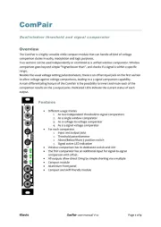
Voltage-controlled multiple-input logic and gate processor
Introduction
Built on the foundations of its acclaimed predecessor, this new version drastically expands the up
feature set within the same footprint. All the original goodies are still there, now enriched by a
full list of state- functions including a delay line Fast processing allows perfect based logic . er
handling of audio signals. User editable settings are stored in non-volatile memory.
With its versatility and features never seen before, the Klavis Logica XT will arouse your creativity
and bring inventiveness to your soundscapes.
Logica
Logica
Logica
LogicaLogica
Features at a glance
14 modes of operation:
o 6 logic functions basic
o 2 forced states
o 6 advanced logic functions:
The Gater adds-up multiple gate signals while
maintaining triggering with adjustable retrigger each
gap time
Gate to trigger with adjustable pulse length
Chronological sequence validation (safe locker)
Toss a coin with dierent chance weighs from the 3
inputs
Flip-op with separate Set and Reset
Digital Sample & hold, with adjustable delay/memory
line (from milliseconds to several seconds)
3 normalized input jacks + user dened manual button for quad
signal handling
Settings stored in non-volatile memory
Simultaneously normal and inverted outputs (e.g. And & Nand)
Dedicated divider by two output
Continuous manual + Bipolar CV control of the mode
LED column telling the current operation mode
LEDs on all outputs indicating the state
LED on manual button indicating its default status
Low consumption, ski-friendly compact module &

Logica
Logica
Logica
Logica Logica user manual V1.1 Page of 2 11
Installation and security
Purpose
This module is meant for installation in a Eurorack-compliant chassis.
It adheres to Doepfer Eurorack mechanical and electrical specications.
Do not attempt using this module in other mechanical or electrical contexts.
Installation
Before the installation, disconnect the mains power supply from your modular system. Some
power supplies are not safely isolated; there is a risk of injury!
See in the specications if this module requires 5V from the supply . If 5V is needed and your rails
rack is not providing 5V, do not attempt connection!
Check that the current consumption requirements of this module, when added to your installed
set of modules do not exceed the available current from your supply. This is done by adding up
the current draw of all modules (mA) separately for each of 5V, 12V and -12V rails. If any of these 3
sums exceeds the available current of your supply for that voltage, do not connect the module to
your system; you need a stronger power supply.
The provided supply at cable can only be inserted in the appropriate orientation at the back of
the module, so there is no risk of error on that end. However, you should pay attention to the
orientation of the cable in the socket of the supply PCB inside your chassis. Cheap sockets
without shrouding may allow you to plug in the connector the wrong way!
The red stripe on the cable should match a stripe printed on the supply board. The stripe also
indicates the -12V side. In case there is no stripe, a -12V marking is a safe indication of the
orientation.
Double check that the connectors are fully inserted and correctly oriented before switching on
the power supply. In case of an anomaly, switch o the power supply immediately and check
everything again.
Factory reset
The module has a number of user editable settings. In case you experience unexpected result this
may due to polarity and/or delay settings that are inadequate for the current purpose.
In case you re lost, you can restart fresh by resetting all settings to their default value. This is ’
done by maintaining the Manual and Xtra buttons pressed before applying power to your case.
You can release the buttons after a couple of seconds. Keep the supply on for at least 10 seconds
after a reset procedure for the default data to be stored in memory.

Logica
Logica
Logica
Logica Logica user manual V1.1 Page of 3 11
Quick overview
The Logica XT combines up to 3 inputs and a push button to realize logic operations.
The functions are split into two main categories:
Simple logic operations (left column of the panel) are indicated by one LED
Advanced logic operations (right column on the panel) are indicated by a LED pair
Switching between the columns is done by a short press of the Xtra button.
The potentiomer selects a function in the column.
For some functions, a long press on the Xtra button allows editing related settings .
Changes are saved automatically without user intervention.
The module is delivered ready to use with sensib predened settings. le
LEDs
All outputs have LEDs that indicate a logic level 1 when on.
The manual button LED tells the setting of the button; the LED is ON when level is one.
Inputs & outputs
Input jacks 1, 2 and 3
With simple logic functions, these all work in the same way. Any signal can be brought to any
jack.
Normalization
With simple logic, unused jacks automatically get the necessary default value so that it is not
needed to replicate a signal if less than 3 inputs are required. This is called “normalization”.
Normalization allows having a logic condition being realized with signals than inputs. For fewer
example, a 2-input AND function would not work if the unused jack(s) were not normalized: the
condition where all inputs go on would not be possible without patching (duplicating) one of the
signals to the remaining input . Normalization is solving that for you. (s)
Contrarily to the usual scheme where normalized inputs are chained, in the Logica XT, it is not
required using the jacks in preferred order for the normalization to work. This is why the usual a
arrows printed between jacks to indicate the normalization order are missing.
Could the Logica XT clever jack behavior be called “cleverized” ?
Main output (Out)
This output provides the logic result of the operation currently selected.
Product specificaties
| Merk: | Klavis |
| Categorie: | Niet gecategoriseerd |
| Model: | Logica XT |
Heb je hulp nodig?
Als je hulp nodig hebt met Klavis Logica XT stel dan hieronder een vraag en andere gebruikers zullen je antwoorden
Handleiding Niet gecategoriseerd Klavis

30 Januari 2025
30 Januari 2025

3 Juli 2024

3 Juli 2024

1 Maart 2024

1 Maart 2024

1 Maart 2024

1 Maart 2024

9 November 2023

22 Mei 2023
Handleiding Niet gecategoriseerd
- Neff
- Siemon
- Silvergear
- Andover
- Hercules
- ChargeHub
- WAGAN
- Telstra
- Audiovox
- Nanni
- MSpa
- QuickMill
- F40C4TMP
- Hasselblad
- Fusion
Nieuwste handleidingen voor Niet gecategoriseerd

14 September 2025

14 September 2025

13 September 2025

13 September 2025

13 September 2025

13 September 2025

13 September 2025

13 September 2025

13 September 2025

13 September 2025