Texas Instruments MSP430F112 Handleiding
Texas Instruments Niet gecategoriseerd MSP430F112
Bekijk gratis de handleiding van Texas Instruments MSP430F112 (32 pagina’s), behorend tot de categorie Niet gecategoriseerd. Deze gids werd als nuttig beoordeeld door 3 mensen en kreeg gemiddeld 4.9 sterren uit 2 reviews. Heb je een vraag over Texas Instruments MSP430F112 of wil je andere gebruikers van dit product iets vragen? Stel een vraag
Pagina 1/32
SLAS256D − NOVEMBER 1999 − REVISED SEPTEMBER 2004
1
POST OFFICE BOX 655303 • DALLAS, TEXAS 75265
DLow Supply Voltage Range 1.8 V to 3.6 V
DUltralow-Power Consumption:
− Active Mode: 200 µA at 1 MHz, 2.2 V
− Standby Mode: 0.8 µA
− Off Mode (RAM Retention): 0.1 µA
DWake-Up From Standby Mode in less
than 6 µs
D16-Bit RISC Architecture, 125 ns
Instruction Cycle Time
DBasic Clock Module Configurations:
− Various Internal Resistors
− Single External Resistor
− 32 kHz Crystal
− High Frequency Crystal
− Resonator
− External Clock Source
D16-Bit Timer_A With Three
Capture/Compare Registers
DSerial Onboard Programming,
No External Programming Voltage
Needed
DFamily Members Include:
MSP430F110:1KB + 128B Flash Memory
128B RAM
MSP430F112:4KB + 256B Flash Memory
256B RAM
DAvailable in a 20-Pin Plastic Small-Outline
Wide Body (SOWB) Package and 20-Pin
Plastic Thin Shrink Small-Outline Package
(TSSOP)
DFor Complete Module Descriptions, Refer
to the MSP430x1xx Family User’s Guide,
Literature Number SLAU049
description
The Texas Instruments MSP430 family of ultralow power microcontrollers consist of several devices featuring
different sets of peripherals targeted for various applications. The architecture, combined with five low power
modes is optimized to achieve extended battery life in portable measurement applications. The device features
a powerful 16-bit RISC CPU, 16-bit registers, and constant generators that attribute to maximum code efficiency.
The digitally controlled oscillator (DCO) allows wake-up from low-power modes to active mode in less than 6µs.
The MSP430F11x series is an ultralow-power mixed signal microcontroller with a built in 16-bit timer and
fourteen I/O pins.
Typical applications include sensor systems that capture analog signals, convert them to digital values, and then
process the data and display them or transmit them to a host system. Stand alone RF sensor front-end is another
area of application.
Copyright 1999 − 2004, Texas Instruments Incorporated
!"# $"%&! '#(
'"! ! $#!! $# )# # # "#
'' *+( '"! $!#, '# #!#&+ !&"'#
#, && $##(
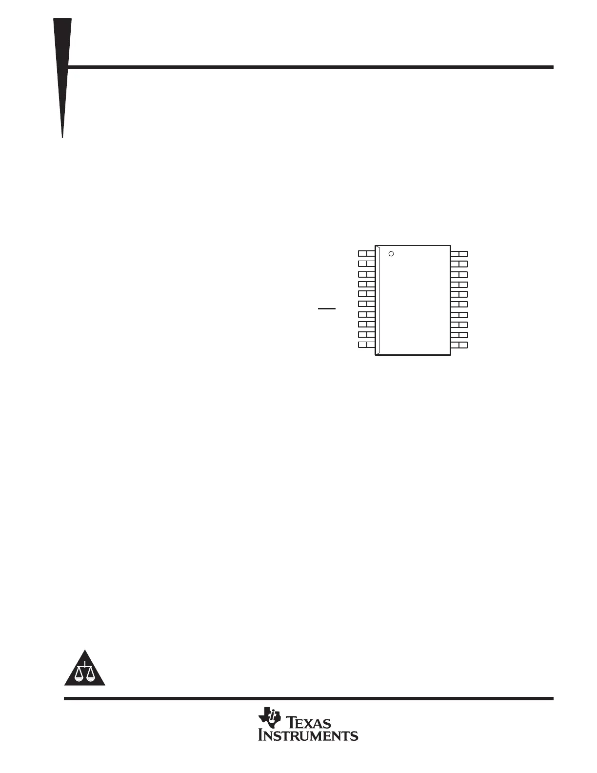
1
2
3
4
5
6
7
8
9
10
20
19
18
17
16
15
14
13
12
11
TEST
V
CC
P2.5/R
osc
V
SS
XOUT/TCLK
XIN
RST
/NMI
P2.0/ACLK
P2.1/INCLK
P2.2/TA0
P1.7/TA2/TDO/TDI
P1.6/TA1/TDI
P1.5/TA0/TMS
P1.4/SMCLK/TCK
P1.3/TA2
P1.2/TA1
P1.1/TA0
P1.0/TACLK
P2.4/TA2
P2.3/TA1
DW OR PW PACKAGE
(TOP VIEW)
Please be aware that an important notice concerning availability, standard warranty, and use in critical applications of
TexasInstruments semiconductor products and disclaimers thereto appears at the end of this data sheet.
Product specificaties
| Merk: | Texas Instruments |
| Categorie: | Niet gecategoriseerd |
| Model: | MSP430F112 |
Heb je hulp nodig?
Als je hulp nodig hebt met Texas Instruments MSP430F112 stel dan hieronder een vraag en andere gebruikers zullen je antwoorden
Handleiding Niet gecategoriseerd Texas Instruments

23 April 2026
22 April 2026
21 April 2026
21 April 2026
20 April 2026
14 April 2026
14 April 2026
13 April 2026
13 April 2026
11 April 2026
Handleiding Niet gecategoriseerd
Nieuwste handleidingen voor Niet gecategoriseerd
25 April 2026
25 April 2026
25 April 2026
25 April 2026
25 April 2026
25 April 2026
25 April 2026
25 April 2026
25 April 2026
24 April 2026