Texas Instruments MAX3222E Handleiding
Texas Instruments Niet gecategoriseerd MAX3222E
Bekijk gratis de handleiding van Texas Instruments MAX3222E (30 pagina’s), behorend tot de categorie Niet gecategoriseerd. Deze gids werd als nuttig beoordeeld door 3 mensen en kreeg gemiddeld 4.4 sterren uit 4 reviews. Heb je een vraag over Texas Instruments MAX3222E of wil je andere gebruikers van dit product iets vragen? Stel een vraag
Pagina 1/30
MAX3222E 3V to 5.5V Multichannel RS-232 Line Driver and Receiver With ±15kV ESD
Protection
1 Features
•ESD Protection for RS-232 bus pins
–±15kV Human-body model (HBM)
–±8kV IEC61000-4-2, Contact discharge
–±15kV IEC61000-4-2, Air-gap discharge
•Meets or exceeds the requirements of TIA/
EIA-232-F and ITU v.28 standards
•Operates with 3V to 5.5V V
CC
supply
•Operates up to 500kbit/s
•Two drivers and two receivers
•Low standby current: 1μA typical
•External capacitors: 4 × 0.1μF
•Accepts 5V logic input with 3.3V supply
•Alternative high-speed pin-compatible device
(1Mbit/s) for SNx5C3222E
2 Applications
•Industrial PCs
•Wired networking
•Data center and networking equipment
•Notebooks
•Hand-held equipment
3 Description
The MAX3222E consists of two line drivers, two line
receivers, and a dual charge-pump circuit with ±15kV
ESD protection pin to pin (serial-port connection pins,
including GND).
The device meets the requirements of TIA/EIA-232-
F and provides the electrical interface between
an asynchronous communication controller and the
serial-port connector. The charge pump and four small
external capacitors allow operation from a single 3V
to 5.5V supply. The device operates at typical data
signaling rates up to 500kbit/s and a maximum of
30V/μs driver output slew rate.
The MAX3222E can be placed in the power-down
mode by setting the power-down ( PWRDOWN) input
low, which draws only 1μA from the power supply.
When the device is powered down, the receivers
remain active while the drivers are placed in the
high-impedance state. Also, during power down, the
onboard charge pump is disabled; V+ is lowered to
V
CC
, and V– is raised toward GND. Receiver outputs
also can be placed in the high-impedance state by
setting enable ( EN) high.
Package Information
PART NUMBERPACKAGE
(1)
PACKAGE SIZE
(2)
MAX3222E
DB (SSOP, 20)7.2mm x 7.8mm
DW (SOIC, 20)12.8mm x 10.3mm
PW (TSSOP, 20)6.5mm x 6.4mm
DGS (VSSOP, 20)5.1mm x 4.9mm
(1)For more information, see Section 11.
(2)The package size (length × width) is a nominal value and
includes pins, where applicable.
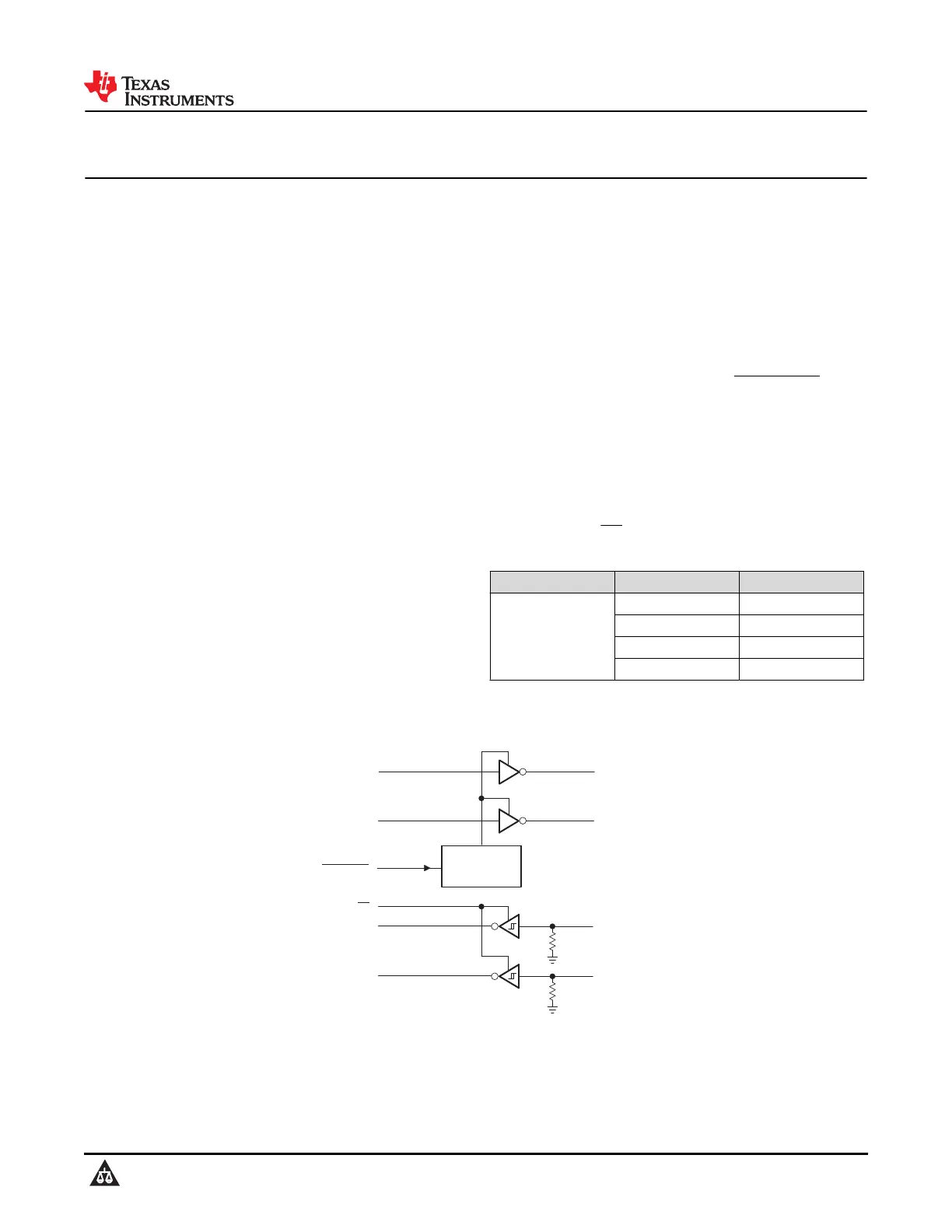
DIN2
DOUT2
128
Powerdown
RIN1
16
20
15
PWRDOWN
ROUT1
DIN1
DOUT1
1317
RIN2
910
ROUT2
1
EN
5 kW
5 kW
Pin numbers are for the DB, DW, and PW packages.
Logic Diagram (Positive Logic)
MAX3222E
SLLS708E – JANUARY 2006 – REVISED DECEMBER 2024
An IMPORTANT NOTICE at the end of this data sheet addresses availability, warranty, changes, use in safety-critical applications,
intellectual property matters and other important disclaimers. PRODUCTION DATA.
Product specificaties
| Merk: | Texas Instruments |
| Categorie: | Niet gecategoriseerd |
| Model: | MAX3222E |
Heb je hulp nodig?
Als je hulp nodig hebt met Texas Instruments MAX3222E stel dan hieronder een vraag en andere gebruikers zullen je antwoorden
Handleiding Niet gecategoriseerd Texas Instruments

23 April 2026
22 April 2026
21 April 2026
21 April 2026
20 April 2026
14 April 2026
14 April 2026
13 April 2026
13 April 2026
11 April 2026
Handleiding Niet gecategoriseerd
Nieuwste handleidingen voor Niet gecategoriseerd
25 April 2026
25 April 2026
25 April 2026
25 April 2026
24 April 2026
24 April 2026
24 April 2026
24 April 2026
24 April 2026
24 April 2026