Epcom VTG48A Handleiding
Epcom Niet gecategoriseerd VTG48A
Bekijk gratis de handleiding van Epcom VTG48A (16 pagina’s), behorend tot de categorie Niet gecategoriseerd. Deze gids werd als nuttig beoordeeld door 51 mensen en kreeg gemiddeld 4.1 sterren uit 5 reviews. Heb je een vraag over Epcom VTG48A of wil je andere gebruikers van dit product iets vragen? Stel een vraag
Pagina 1/16
Page 1 of 16
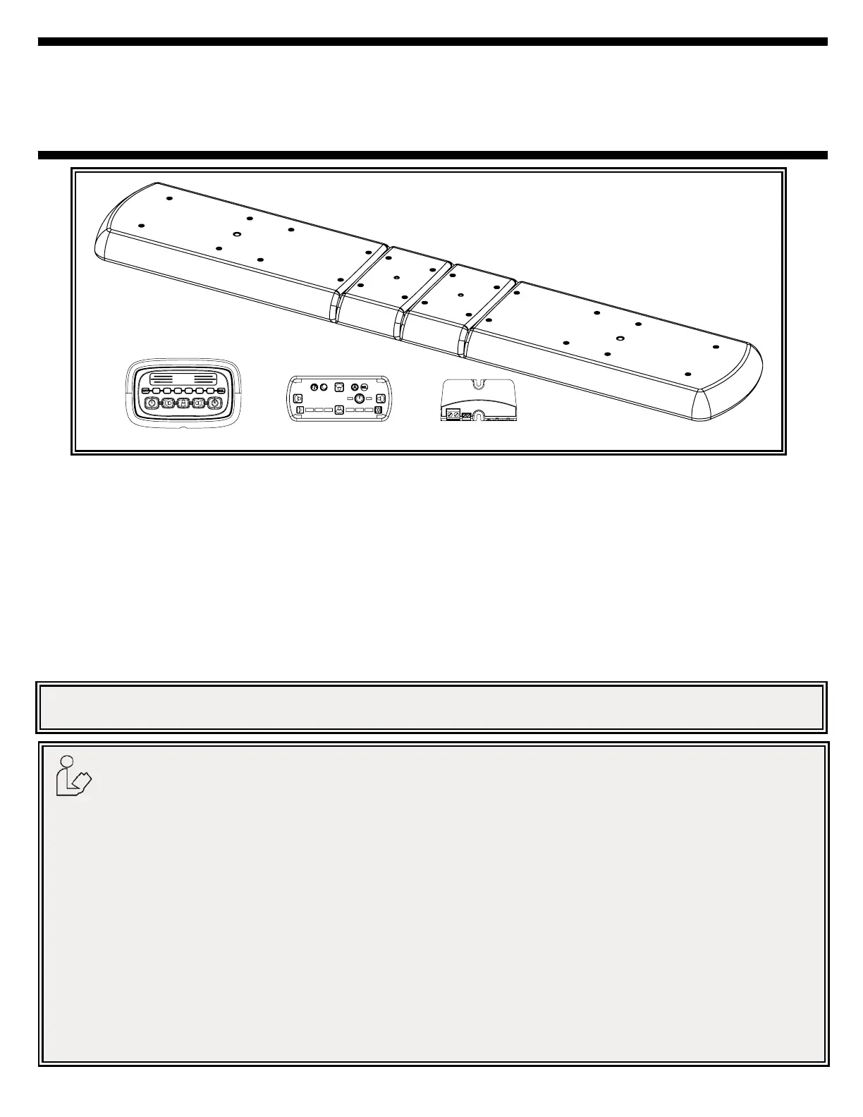
IMPORTANT!Read all instructions before installing and using. Installer: This manual must be
delivered to the end user. This manual assumes installation by a suitably qualied Automotive Technician.
Installation and Operation Instructions
12+ Series Vantage™ Lightbars
Lightbar Control Options
Introduction:
12+ Series Lightbars are versatile and powerful warning devices suitable for a range of vehicle types and duties. There are numerous op-
tions and lengths available. The lightbars can either be mounted permanently to the vehicle or mounted using an optional roof mounting kit.
The 12+ Series Lightbar features a durable aluminu dules: Warning modules, Stop-Tail-Turn modules, and white Alley/Takedown/Worklight
modules.
Unpacking and Pre-Installation:
Carefully remove the lightbar and place it on a at surface. Examine the unit for transit damage and locate all parts. If damage is found or
parts are missing, contact the transit company. Do not use damaged or broken parts.
Ensure the lightbar voltage is compatible with the planned installation.
Do not install and/or operate this safety product unless you have read and understand the safety
information contained in this manual.
1.Proper installation combined with operator training in the use, care and maintenance of emergency warning devices are essential to
ensure the safety of emergency personnel and the public.
2.Emergency warning devices often require high electrical voltages and/or currents. Exercise caution when working with live electrical
connections.
3.This product must be properly grounded. Inadequate grounding and/or shorting of electrical connections can cause high current
arcing, which can cause personal injury and/or severe vehicle damage, including re.
4.Proper placement and installation is vital to the performance of this warning device. Install this product so that output performance of
the system is maximized and the controls are placed within convenient reach of the operator so that s/he can operate the system
without losing eye contact with the roadway.
5.It is the responsibility of the vehicle operator to ensure daily that all features of this product work correctly. In use, the vehicle operator
should ensure the projection of the warning signal is not blocked by vehicle components (i.e., open trunks or compartment doors),
people, vehicles or other obstructions.
6.The use of this or any other warning device does not ensure all drivers can or will observe or react to an emergency warning signal.
Never take the right-of-way for granted. It is your responsibility to be sure you can proceed safely before entering an intersection, drive
against trafc, respond at a high rate of speed, or walk on or around trafc lanes.
7.This equipment is intended for use by authorized personnel only. The user is responsible for understanding and obeying all laws
regarding emergency warning devices. Therefore, the user should check all applicable city, state, and federal laws and regulations.
The manufacturer assumes no liability for any loss resulting from the use of this warning device.
8.This product may contain high intensity LEDs staring directly into these lights could result in temporary and/or permanent vision
impairment.
Product specificaties
| Merk: | Epcom |
| Categorie: | Niet gecategoriseerd |
| Model: | VTG48A |
| Breedte: | 1219.2 mm |
| Diepte: | 279.4 mm |
| Hoogte: | 63.5 mm |
| Aantal lampen: | 64 lampen |
| Soort lamp: | LED |
| Stroom: | 11 A |
| Type stroombron: | DC |
| DC voltage input: | 12 - 24 V |
| Aantal: | 1 |
| Bedrijfstemperatuur (T-T): | -30 - 50 °C |
| Type product: | Lichtbalk |
| Aantal lichteffecten: | 48 |
Heb je hulp nodig?
Als je hulp nodig hebt met Epcom VTG48A stel dan hieronder een vraag en andere gebruikers zullen je antwoorden
Handleiding Niet gecategoriseerd Epcom

6 Januari 2024
6 Januari 2024
6 Januari 2024
6 Januari 2024
6 Januari 2024
6 Januari 2024
6 Januari 2024
6 Januari 2024
6 Januari 2024
6 Januari 2024
Handleiding Niet gecategoriseerd
Nieuwste handleidingen voor Niet gecategoriseerd
8 Juni 2026
8 Juni 2026
8 Juni 2026
8 Juni 2026
8 Juni 2026
8 Juni 2026
8 Juni 2026
8 Juni 2026
8 Juni 2026
8 Juni 2026