Epcom X7945A Handleiding


Lees hieronder de 📖 handleiding in het Nederlandse voor Epcom X7945A (4 pagina's) in de categorie Niet gecategoriseerd. Deze handleiding was nuttig voor 7 personen en werd door 2 gebruikers gemiddeld met 4.5 sterren beoordeeld

Pagina 1/4
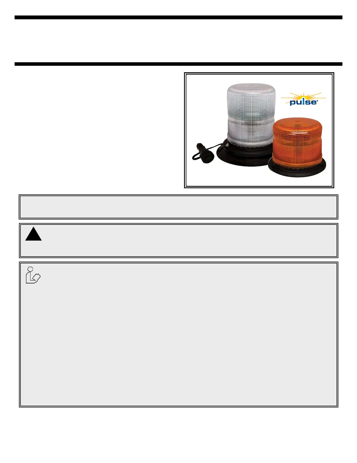
The 7945 & 7950 series LED beacons are designed to
meet SAE J845 Class II specications (Amber and Clear
only). The 7945 & 7950 features 12-48 VDC operation, 3
bolt mounting ange, integrated 1” pipe mount, & optional
vacuum-magnet mount.
Page 1 of 4
Do not install and/or operate this safety product unless you have read and understand the
safety information contained in this manual.
1. Proper installation combined with operator training in the use, care, and maintenance of emergency warning devices
are essential to ensure the safety of you and those you are trying to protect.
2. Exercise caution when working with live electrical connections.
3. This product must be properly grounded. Inadequate grounding and/or shorting of electrical connections can cause
high current arcing, which can cause personal injury and/or severe vehicle damage, including re.
4. Proper placement and installation are vital to the performance of this warning device. Install this product so that out-
put performance of the system is maximized and the controls are placed within convenient reach of the operator so
that s/he can operate the system without losing eye contact with the roadway.
5. It is the responsibility of the vehicle operator to ensure during use that all features of this product work correctly. In
use, the vehicle operator should ensure the projection of the warning signal is not blocked by vehicle components
(i.e., open trunks or compartment doors), people, vehicles, or other obstructions.
6. The use of this or any other warning device does not ensure all drivers can or will observe or react to a warning sig-
nal. Never take the right-of-way for granted. It is your responsibility to be sure you can proceed safely before enter-
ing an intersection, driving against trafc, responding at a high rate of speed, walking on or around trafc lanes.
7. This equipment is intended for use by authorized personnel only. The user is responsible for understanding and
obeying all laws regarding warning signal devices. Therefore, the user should check all applicable city, state, and fed-
eral laws and regulations. The manufacturer assumes no liability for any loss resulting from the use of this warning
device.
WARNING!
Failure to install or use this product according to manufacturer’s recommendations may result in property
damage, serious bodily/personal injury, and/or death to you and those you are seeking to protect!
!
IMPORTANT! Read all instructions before installing and using. Installer: This manual must be
delivered to the end user.
Installation Instructions
360° LED Beacon
Caution: When drilling into any vehicle surface,
make sure that the area is free from any electrical wires,
fuel lines, vehicle upholstery, etc. that could be damaged.
Specications:
Size: 7945: 6.0” dia. x 4.8” high
7950: 6.0” dia. x 6.8” high
Weight: approx. 3 lbs.
Input Voltage: 12-48 VDC system
Input Current: 0.5A @ 12.8 VDC
Maximum power consumption: 6.4 Watts
Temp. Range: -30°C to +50°C
Carefully remove the beacon and place it on a at surface. Examine
the unit for transit damage, and locate all parts. If damage is found,
or parts are missing, contact the transit company. Do not use dam-
aged or broken parts.
Permanent Mounting:
Select the desired location on a at surface for the LED beacon to
be mounted. The visibility of the ash and ease of wiring access
should be taken into consideration in the selection of the mounting
location.
1. Using the base gasket as a template, mark the three mount-
ing hole locations (see Figure 1).
2. Drill the holes using a 7/32” drill size.
3. A fourth hole may be drilled for wire access as shown in Fig-
ure 1, or the wires may be routed through the slot in the base
for external access.
4. Connect the power wires as shown in the wiring section (see
Figure 3).
5. Mount the beacon with #8 hardware.
Pipe Mounting:
The 7945 & 7950 series base comes with 1” NPT threads for pipe
mounting.
Figure 1
Temporary Mounting, Vacuum-Magnet Mount:
The 7945 & 7950 series beacons are available as vacuum-magnet
mount (7945X-VM & 7950X-VM) units. The Vacuum-Magnet Mount
feature includes a suction cup on the bottom of the beacon, with a
magnet inside of the suction cup, for a secure, temporary mount. The
beacon should be placed in the center of the roof where the least
amount of curvature occurs. Before installing, make sure there is
no debris on the bottom of the beacon or on the roof of the vehicle,
which could reduce the holding power of the suction cup and mag-
net. Place and remove the beacon without sliding to avoid scratching
the paint on the vehicle. After placement, the beacon should adhere
rmly to the surface. If the unit slides or moves easily, a proper in-
stallation has not been obtained. To release the vacuum, lift the tab
to release the airlock (see Figure 2). To protect the Vacuum-Magnet
Mount assembly, return beacon to the box when not in use. Do not
attempt to attach the beacon to an ice-covered surface.
Page 2 of 4
Important! This unit is a safety device, and it must be
connected to its own seperate, fused power point to as-
sure its continued operation should any other electrical
accessory fail.
!
WARNING!
Maximum recommended vehicle speed for safe operation
using the Vacuum Mount model is 65 mph (104 km/h), when tted
to the center of a vehicle roof of steel construction. Higher speeds
could cause the mount to fail, resulting in the beacon ying off
of the vehicle, which could cause damage to other vehicles, and
injury or death to the passengers. The vacuum-magnet mount is not
intended as a permanent mounting for the beacon. The vacuum-
magnet mount unit must be mounted on a at smooth magnetic
surface (i.e. no berglass, ribbed style roofs, etc.). Insure that the
magnet is kept clean.
!
Figure 2
Installation & Mounting:
WARNING!
Failure to follow these instructions can result in re or injury from excessive heat build up.
Operator is responsible for ensuring cigarette adapter ts correctly into cigarette/auxillary outlet used.
For proper operation, verify cigarette/auxillary outlet circuit is rated to supply, a minimum of 10 amps. (See specications
section for rated current in amperes).
Do not exceed the current rating for the cigarette lighter power outlet recommended by vehicle manufacturer.
Keep cigarette lighter adapter, and outlet, clean and free of debris.
Do not use the cigarette lighter adapter when wet.
Insert cigarette lighter adapter fully into the outlet for proper connection.
Grasp cigarette lighter adapter, NOT cord, to remove from outlet.
Remove cigarette lighter adapter completely from outlet when light is not in use.
Wiring Instructions:
Important: Disable power before wiring the beacon.
Page 3 of 4
Notes:
1. Larger wires and tight connections will provide longer service life for components. For high current wires it is highly
recommended that terminal blocks or soldered connections be used with shrink tubing to protect the connections. Do
not use insulation displacement connectors (e.g., 3M Scotchlock type connectors).
2. Route wiring using grommets and sealant when passing through compartment walls. Minimize the number of splices
to reduce voltage drop. High ambient temperatures (e.g., under-hood) will signicantly reduce the current carrying
capacity of wires, fuses, and circuit breakers. All wiring should conform to the minimum wire size and other recom-
mendations of the manufacturer and be protected from moving parts and hot surfaces. Looms, grommets, cable ties,
and similar installation hardware should be used to anchor and protect all wiring.
3. Fuses or circuit breakers should be located as close to the power takeoff points as possible and properly sized to
protect the wiring and devices.
4. Particular attention should be paid to the location and method of making electrical connections and splices to protect
these points from corrosion and loss of conductivity.
5. Ground termination should only be made to substantial chassis components, preferably directly to the vehicle battery.
6. Circuit breakers are very sensitive to high temperatures and will “false trip” when mounted in hot environments or
operated close to their capacity.
(+) (-)
RED
BLACK
GROUND
GROUND
SWITCH
(USER SUPPLIED)
FUSE (3 AMP)
(USER SUPPLIED)
YELLOW
FLASH PATTERN SELECT
(ISOLATE WHEN NOT IN USE)
Figure 3
Maintenance:
This LED beacon has been designed for trouble free operation.
There are no periodic maintenance needs for this model.
Troubleshooting:
1. Most beacon failures, including intermittent or erratic operation
as well as failure of operation can be traced to wiring or battery
problems. Check all wiring, connections, fuse, switch, and bat-
tery voltage to insure that the correct voltage is reaching the
beacon.
2. If this has not remedied the problem, return product to your local
dealer for warranty replacement.
Note: Operating the vehicle without the lens installed on
this product will result in damage that will not be covered
under warranty.
Flash Pattern Selection:
Flash patterns can be selected by touching the yellow wire to the
red power wire for less than a second. Contacting the yellow and red
wires for longer than a second toggles to the preceding ash pattern.


Product specificaties

Merk: Epcom
Categorie: Niet gecategoriseerd
Model: X7945A
Kleur van het product: Zwart
Soort: Vast
Gebruikershandleiding: Ja
Materiaal behuizing: Aluminium
Aantal lampen: 6 gloeilamp(en)
Type lamp: LED
Soort lamp: LED
Vormfactor: Rond
Type stroombron: DC
Certificering: SAE J845 Class 2, CE, R10, RoHS
Aantal per verpakking: 1 stuk(s)
Aantal: 2
Kleur licht: Blue, Clear, White
Stroomverbruik: 1 mA
LED kleur: Amber
Maximale wattage van vervangende lamp: 5 W
Gemakkelijk te installeren: Ja
Lamp(en) meegeleverd: Ja
Bedrijfstemperatuur (T-T): -40 - 65 °C
Type product: Reservelamp
Aantal lichteffecten: 12
Bevestigingstype: Schroeven
Diffusor kleur: Amber
Diffusor betekenis: Opgelet

Heb je hulp nodig?

Als je hulp nodig hebt met Epcom X7945A stel dan hieronder een vraag en andere gebruikers zullen je antwoorden


Handleiding Niet gecategoriseerd Epcom

Handleiding Niet gecategoriseerd

Nieuwste handleidingen voor Niet gecategoriseerd