Camille Bauer Sineax VS50 Handleiding

Camille Bauer Receiver Sineax VS50

Lees hieronder de 📖 handleiding in het Nederlandse voor Camille Bauer Sineax VS50 (4 pagina's) in de categorie Receiver. Deze handleiding was nuttig voor 20 personen en werd door 2 gebruikers gemiddeld met 4.5 sterren beoordeeld

Pagina 1/4
Reaktionszeit (10-90%)
Übertragung :
Übertragungsfehler max. :
Auflösung :
Temperaturdrift :
Fehler bei der SQRT :
Fehler bei der Linearisierung
des zylindrischen Tanks :
(1)
(1)
(2) (3)
(2)
:bei 50 Hz max. 41 ms ohne Filter und 88 ms mit Filter;
bei 60 Hz max. 35 ms ohne Filter und 74 ms mit Filter.
Optisch-digital
0,08% des Vollausschlags für denAusgang mAoder5 V
0.07% des Vollausschlags für denAusgang 10 V
1 mV für den Spannungsausgang, 2 A für den
Stromausgang
< 120 ppm/K
Im Bereich von 1..100%: 32-bit-floating-point Format
0,05%
m
DEUTSCH - 1/8 DEUTSCH - 5/8 DEUTSCH - 7/8
DEUTSCH - 2/8 DEUTSCH - 6/8 DEUTSCH - 8/8
DEUTSCH - 3/8
DEUTSCH - 4/8
SPANNUNG/STROM-WANDLER
MIT GALVANISCHER DREIPUNKTISOLIERUNG
Allgemeine Beschreibung
Das Gerät VS50 ist ein Wandler mit galvanischer Dreipunktisolierung, für nach
Industriestandard übliche Spannungs- oder Stromsignale, mit passivem Eingang und
aktivem Ausgang. Die Analog-Digital-Wandlung erfolgt mit einer Auflösung von 14 bit
r jeden Eingangsbereich.
Der Wandler weist außerdem noch folgende Funktionen auf:
Programmierbare Störfrequenzunterdrückung für 50 oder 60 Hz Netzfrequenz
Zuschaltbarer Filter für die Stabilisierung der Anzeige
Invertierbarer Eingang und invertierte Ausgangsskalen
Programmierbarer Overrange-Bereich (auf 2,5% oder 5%)
Quadratwurzelermittlung
Linearisierung für zylindrische, horizontale Tanks
Die Eigenschaften des Wandlers sind die stark begrenzten Abmessungen (6,2 mm), die
Verankerung auf DIN-Schiene zu 35 mm, die Möglichkeit der Speisung über Bus, die
schnellen Anschlüsse über Federklemmen, die galvanische 3-Wege Trennung und die
Konfigurierbarkeit vor Ort über DIP-Schalter.
Technische Eigenschaften
Spannungsversorgung :
Leistungsaufnahme :
19,2..30 Vdc
Max. 22 mAbei24 Vdc (mit Stromausgang von20 mA)
Spannungseingang (max. 50 V) :
Spannungseingang (max. 30 V) :
Stromeingang (max. 24 V) :
Zugelassener Eingangs-
Overrange-Bereich :
0..15 V, 0..30 V, Eingangsimpedanz: 325 k
0..10 V, 2..10 V, 0..5 V, 1..5 V,
Eingangsimpedanz: 110 k
0..20 mA, 4..20 mA, Eingangsimpedanz: 35
± 2,5 oder ± 5%, je nach Einstellung (siehe Abschnitt
“Overrange-Grenzwerte“)
Ω
Ω
Ω
Digital, Bearbeitung im 32-Bit-Floating-Point-Format
14 bit für jeden Eingangsbereich
Verarbeitung :
ADC :
0..5 Vdc, 1..5 Vdc,0..10 Vdcund 10..0 Vdc
Min. Lastwiderstand: 2 k
0..20 mA, 4..20 mA, 20..0 mAund20..4 mA
Max. Lastwiderstand: 500
unverstellbar (siehe Abs chni tt Overrange-
Grenzwerte”)
anhernd 25 mA
Ω
Ω
Ausgangsspannung
Ausgangsstrom
Zugelassene Overrange-
Höchstgrenzwert :
Strom Ausgangsschutz
:
:
:
Isolierungsspannung :
Schutzart:
Umgebungsbedingungen :
Lagertemperatur :
LED-Anzeigen :
Anschlüsse :
Leiterquerschnitt :
Abisolierung der Leiter :
Normen :
Abmessungen, Gewicht :
1,5 kV zwischen allen Portpaaren
IP20
Temperatur -20..+65 °C
Luftfeuchtigkeit 30..90 %, nicht kondensierend
Einsatzhöhe: bis 2000 m über dem Meeresspiegel
-40..+85 °C
Begrenzung des Eingangs-oder Ausgangs-Overrange-
Bereichs, Sättigung des Eingangs, interner Schaden.
Federklemmen
0,2..2,5 mm
8 mm
2
EN61000-6-4/2002 elektromagnetische Emission,
ind strielle Umgebung)
EN61000-6-2/2005
EN61010-1/2001
(
u
(elektromagnetische Immunität,
industrielle Umgebung)
(Sicherheit)
Alle Schaltungen müssen mit doppelter Isolierung gegen
Schaltungen mit gefährlicher Spannung isoliert werden.
Der Speisungstransformator muss der Norm EN60742:
“ I s o l i e r u n g s t r a n s f o r m a t o r e n u n d
Sicherheitstransformatoren” entsprechen.
6,2 x 93,1 x 102,5 mm, 50 g.
Gehäuse : PBT (schwarze Farbe)
(1)Keine Linearisierungsfunktion eingeschalten.
(2)Die Linearisierungsfunktionen arbeiten nur im Nominalbereich von 0…100%, während
im Underrange- und im Overrange-Bereich das Eingangssignal ohne jegliche
Veränderung (G=1) übertragen wird. Die Kontinuität und die Gleichmäßigkeit der
Übertragung sind im gesamten messbaren Bereich garantiert.
(3) In der Strecke 0…1% ist die Kurve linear mit einem Gewinn von G=10, um überflüssige
Rauschamplifikation im ersten Teil des Meßbereichs zu vermeiden.
Anweisungen zur Installation
Das Modul ist für die Montage auf Schienen nachDIN 46277 ausgelegt. r eine bessere
Belüftung des Moduls empfehlen wir die Montage in vertikaler Stellung sowie die
Vermeidung der Positionierung in Kanälen oder von sonstigen Gegenständen, die eine
Belüftung behindern.
Vermeiden Sie die Installation des Moduls über Geräten, die Wärme erzeugen; wir
empfehlen die Installation im unteren Bereich der Schalttafel oder des Gehäuses.
Wir empfehlen die Montage auf der Schiene mit dem entsprechenden Anschlussbus
(Bestellnr. CB-Power-Bus), der das Anschließen der Speisung an jedes einzelne Modul
überflüssig macht.
0
1
15
6
7
8
2
3
4
SW1 SW2
POWER
S UPPLY
OUTPUT
INPUT
19.2. .30 Vd c
P < 500 mW
V / I
+
+
-
-
Range : -150..650 °C
Load : R 500 / R 2 k
Test Voltage : 1.5 kV, 50 Hz, 1 min
Amb. T emp. : -20..+ 65 °C
< >
m
WW VI
0
1
1
5
6
7
8
2
3
4
SW1 SW2
POWER
S UPPLY
OUTPUT
INPUT
19.2. .30 Vd c
P < 500 mW
V / I
+
+
-
-
Range : -150..650 °C
Load : R 500 / R 2 k
Test Voltage : 1.5 kV, 50 Hz, 1 min
Amb. T emp. : -20..+ 65 °C
< >
m
W
WV
I
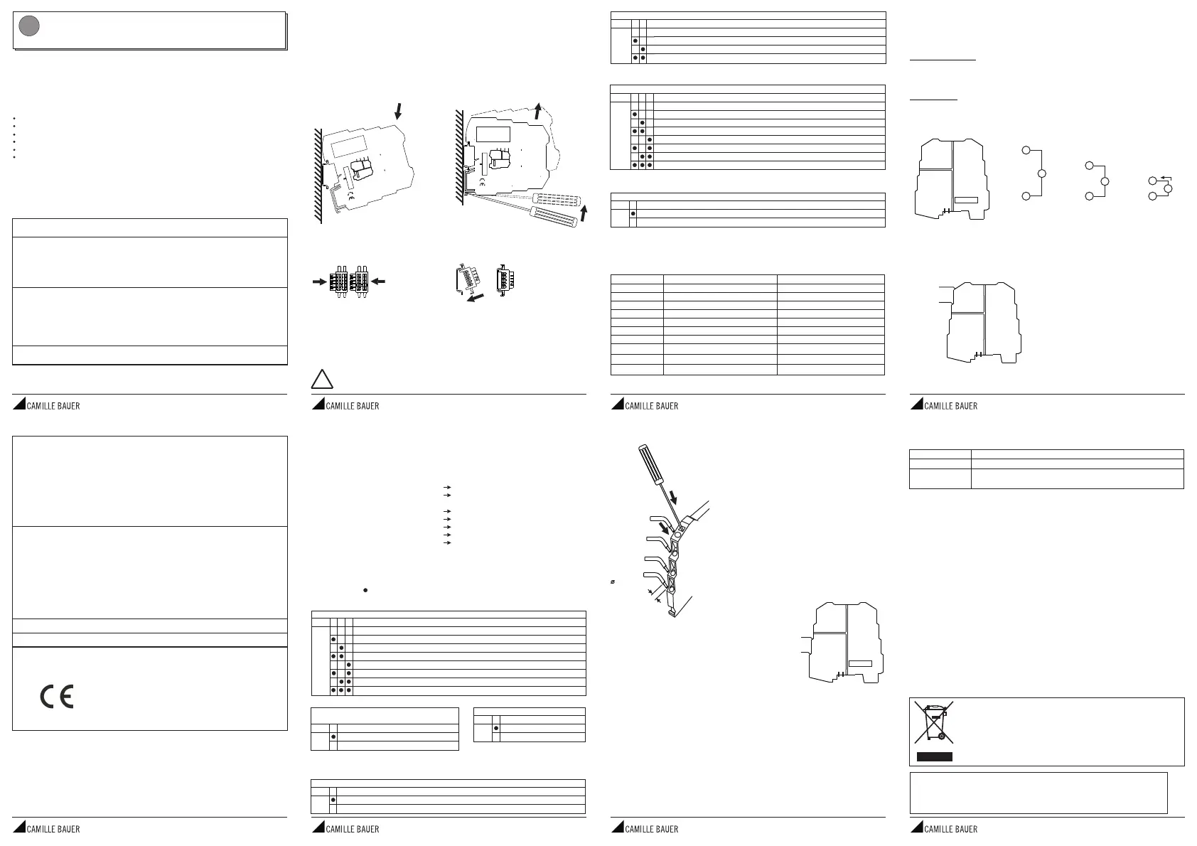
1 - Setzen Sie das Modul in den oberen
Teil der Schiene ein
2 - Drücken Sie das Modul nach unten
1 - Hebeln Sie mit einem Schraubenzieher
(wie auf der Abbildung gezeigt)
2 - Drehen Sie das Modul nach oben
Montage des Moduls in der Schiene Entfernung des Moduls von der Schiene
Einsatz des CB-Power-Bus
1 - Setzen Sie die CB-Power-BusAnschlüssezusammen, umdie erforderlicheAnzahl von
Positionen zu erzielen (jeder CB-Power-Bus gestattet die Aufnahme von 2 Modulen)
2 - Setzen Sie den CB-Power-Bus in die Schiene ein;setzen Sie ihn dazu auf der oberen
Seite ein und drehen Sie ihn nach unten
WICHTIG: Schenken Sie der Position der vorstehenden Klemmen der Busschiene eine
erhöhteAufmerksamkeit. Der CB-Power-Bus muss so in die DIN-Schiene gesetzt werden,
so dass die vorstehenden Klemmen links liegen (wie im Bild), anderenfalls sind die
Wandlerkopfüber montiert.
- Schließen Sie nie die Speisung direkt am Bus der DIN-Schiene an.
- Greifen Sie die Speisung weder direkt, noch über die Klemmender Module ab.
!
Alle DIP-Schalter des Moduls befinden sich in der Position OFF als
Standardkonfiguration.
Obige Einstellungen sind also nur gültig, wenn alle DIP-Schalter auf OFF stehen. Wird
auch nur ein DIP-Schalter verändert, ist es erforderlich, alle anderen Parameter wie folgt
neu einzustellen.
Eingangssignal
Störfrequenzunterdrückung für 50 oder
60 Hz Netzfrequenz
Eingangsfilter
Invertierungsmöglichkeit
Linearisierung
Ausgangssignal
Eingangs-Overrange-Bereich
0..20 mA
50 Hz
Zugeschalten
Nein
Nein
0..20 mA
Grenzwerte 5% limit±
EINSTELLUNG DER DIP-SCHALTER
Werkseinstellung
MERKE: Für alle nachfolgenden Tabellen
Die Angabe von zeigt an, dass der DIP-Schalter in Position ON steht (AN).
Keine Angabe bedeutet, dass der DIP-Schalter in der Position OFF steht (AUS).
EINGANGSSIGNAL
1SW1 2 3
4..20 mA
2..10 Vdc
0..20 mA
0..10 Vdc
1..5 Vdc
0..5 Vdc
0..30 Vdc
0..15 Vdc
STÖRFREQUENZUNTERDRÜCKUNG FÜR
50-60 H NETZFREQUENZz
4SW1
50 Hz
60 Hz
EINGANGSFILTER (*)
5SW1
Nein
Ja
INVERTIERUNGSMÖGLICHKEIT
6SW1
Nein
Ja
AUSGANGSSIGNAL
1SW2 2 3
Nominalwert Overrange-Grenzwert ± 2,5% Overrange-Grenzwert ± 5%
20 mA 20,5 mA 21 mA
4 mA 3,5 mA 3 mA
0 mA 0 mA 0 mA
30 Vdc 30,75 Vdc 31,5 Vdc
15 Vdc 15,375 Vdc 15,75 Vdc
10 Vdc 10,25 Vdc 10,5 Vdc
5 Vdc
1 Vdc
2 Vdc
0 Vdc
5,125 Vdc
0,875 Vdc
1,75 Vdc
0 Vdc
5,25 Vdc
0,75 Vdc
1,5 Vdc
0 Vdc
0..20 mA
4..20 mA
20..0 mA (5)
20..4 mA (5)
0..10 Vdc
0..5 Vdc
1..5 Vdc
2..10 Vdc
(5) Es handelt sich um invertierte Ausgangsskalen. Diese sind dann besonders nützlich,
wenn die angewandte Linearisierung mit der Eingangsinversion nicht kompatibel ist.
EINGANGS-OVERRANGE-BEREICH
4SW2
2.5%
5%
Die programmierbaren Overrange-Grenzwerte, die in der untenstehenden Tabelle
angeführt sind, gelten für das Eingangssignal. Für das Ausgangssignal gelten folgende,
unverstellbare Grenzwerte: 0..21 mA,0..5,25 Vdc, 0..10,5 Vdc.
Overrange-Grenzwerte
FUNKTION
7SW1 8
Vorgabe
Keine
Quadratwurzel (SQRT)
Tank
8 mm
0,2..2,5 mm2
Elektrische Verbindung
Das Modul besitzt Federklemmen für die elektrischen
Anschlüsse.
Nehmen Sie bei den Anschlüssen auf die folgenden
Anweisungen Bezug:
1 EntfernenSie 0,8 cm der Isolierung am Ende der
Kabel
2 hren Sie einen Schraubenzieher in die
quadratische Öffnungein und drücken Sie ihn, bis sich
die Feder öffnet,die das Kabel blockiert
3 hren Sie das Kabel in die runde Öffnungein
4 Ziehen Sie den Schraubenzieher heraus und
überprüfen Sie, ob das Kabel sicher in der Klemme
befestigt ist.
Spannungsversorgung
Es bestehen verschiedene Möglichkeiten für die
Speisung der Module der Serie VS.
1 - Direkte Speisung der Module durch Anschluss
der Speisung von 24 Vdc direkt an die Klemmen
7 (+) und 8 (-) jedes einzelnen Moduls
15
6
7
8
2
3
4
POWER
SUPPLY
OUTPUT
INPUT
19.2..30 Vdc
+
-
2 - Verwendung des Zubehörartikels CB-Power-Bus für die Verteilungder Speisungan die
Module über Bus, wodurchdie Speisung jedes einzelnen Moduls überflüssig wird.
Über den Bus können alle Module gespeist werden; die Gesamtleistungsaufnahme des
Busses muss unter 400 mAliegen. Beigrößeren Leistungsaufnahmenkönnen die Module
beschädigt werden. In die Speisung muss eine entsprechend bemessene Sicherung in
Reihe eingesetzt werden.
3 - Verwendung des Zubehörartikels CB-Power-Bus für die Distribution der Speisung der
Module über Bus sowie des Zubehörartikels VS70 für denAnschluss andie Speisung.
Das VS70 ist ein Modul mit einer Breite von 6,2 mm, das eine Reihe von
Schutzschaltungen zum Schutz der über den Bus angeschlossenen Module gegen
eventuelle Überspannungen aufweist.
Der Bus kann über ein Modul VS70 gespeist werden, falls die Gesamtleistungsaufnahme
des Busses unter 1,5 A liegt. Bei höheren Leistungsaufnahmen können das Modul oder
der Bus beschädigt werden. In die Speisung muss eine entsprechend bemessene
Sicherung inReihe eingesetzt werden.
Input
Das Modul empfängt ein Eingangssignal in Strom oder Spannung.
Wir empfehlen,für den elektrischenAnschluss abgeschirmte Kabel zu verwenden.
Klemme 1:Spannungseingang bis zu 30 Vdc (Belastbarkeit 0..15 Vdc und 0..30 Vdc).
Klemme 2:Spannungseingang bis zu 10 V.
Klemme 4: Rückkehr (GND)
Klemme 3: Stromeingang
Klemme 4: Rückkehr (GND)
Spannungseingang
Stromeingang
Ausgang
Spannungsanschluss - Stromanschluss (Fremdstrom).
Wir empfehlen,für den elektrischenAnschluss abgeschirmte Kabel zu verwenden.
15
6
7
8
2
3
4
POWER
SUPPLY
OUTPUT
INPUT
V / I
+
-
15
6
7
8
2
3
4
POWER
SUPPLY
OUTPUT
INPUT
Spannung
max 30 Vdc
1
4
Spannung
max 10 Vdc
2
4
Strom
3
4
V
V
++
mA
Anmerkung: Zur Reduzierung der Dissipation des Instruments sollte der
Spannungsausgang verwendet oder eine Last von > a r250 m Stromausgang garantie t
werden.
Ω
Anzeige mit LED auf der Front
LED ( )rot Bedeutung
Blinken
Konstantes
Leuchten
Interner Schaden
Hinweis: Bei internem Schaden bleibt derAusgangswert null.
Begrenzung des Eingangs- oder Ausgangs-Overrange-Bereichs
oder Sättigung des Eingangs.
(*) Der Filter erhöht die Störfrequenzunterdrückung und stabilisiert die Anzeige, indem
er das Signalrauschen verringert. Daher ist es besser, den Filter immer zuzuschalten,
außer in den Fällen in denen maximale Reaktionsgeschwindigkeit erfordert wird.
D
SINEAX VS50 - 162983
Entsorgung von alten Elektro und Elektronikgeräten (gültig in der Europäischen Union und anderen
europäischen Ländern mit separatemSammelsystem)
Dieses Symbolauf dem Produkt oder auf der Verpackung bedeutet, dass dieses Produkt nicht wieHausmuII
behandelt werdendarf. Stattdessen solldieses Produkt zudem geeigneten Entsorgungspunktzum Recyclen
von Elektro und Elektronikgeräten gebracht werden. Wird das Produkt korrekt entsorgt, helfen Sie mit,
negativen Umwelteinflüssen und Gesundheitsschäden vorzubeugen, die durch unsachgemäße Entsorgung
verursacht werden könnten. Das Recycling von Material wird unsere Naturressourcen erhalten. Für nähere
Informationen über das Recyclen dieses Produktes kontaktieren Sie bitte Ihr lokales Bürgerbüro, Ihren
Hausmüll Abholservice oder das Geschäft , indem Siedieses Produkt gekauft haben.
SINEAX VS50
SINEAX VS50
SINEAX VS50
SINEAX VS50
SINEAX VS50
SINEAX VS50
SINEAX VS50
SINEAX VS50
MI001860-F/D
Camille Bauer AG
Aargauerstrasse 7
CH-5610 Wohlen/Switzerland
Phone +41 56 618 21 11
Fax +41 56 618 35 35
e-Mail: info@camillebauer.com
http://www.camillebauer.com
10-90% response
Transmission :
Max. transmission error :
Resolution :
Thermal drift :
SQRT error :
Linearisation error Cylindrical
tank :
(1)
(1)
(2) (3)
(2)
:50 Hz : max 41 ms without filter and 88 ms with filter;
60 Hz : max 35 ms without filter and 74 ms with filter.
Digital Optical
0.08% of the f.s. value for mA or 5 V output
0.07% of the f.s. value for 10 V output
1 mV for voltage output, 2 uA for current output
Lower than 120 ppm/K
in the range 1..100%: floating point 32 bit
0,05%
ENGLISH - 1/8 ENGLISH - 5/8 ENGLISH - 7/8
ENGLISH - 2/8 ENGLISH - 6/8 ENGLISH - 8/8
ENGLISH - 3/8
ENGLISH - 4/8
EN
SINEAX VS50 - 162983
V - mA CONVERTER
WITH 3-POINT GALVANIC INSULATION
General Description
The VS50 instrument is a V - mA converter with 3-point galvanic insulation designed for
industrial standard voltage or current signals with passive input and active output.
Analogue/digital conversion takes place at 14 bit on every input range.
The instrument also provides the following functions:
Rejection programmable for 50 or 60 Hz mains frequency.
Additional reading stabilisation filter.
Inversion of the input and inverted output scales
Input Out-of-Range programmable to 2.5% or 5.0%
SQRT function.
Linearisation for horizontal cylindrical tanks.
The module is also characterised by its extremely compact size, coupling to 35 mm DIN
driver, power supply available by bus, quick fit couplings by spring-type terminals, 3-
point insulation, onsite configuration by DIP-switch.
Technical Features
Power supply :
Consumption :
19,2..30 Vdc
Max 22 mA at 24 Vdc ( 20 mA output )
Voltage input (max. 50 V) :
Voltage input (max. 30 V) :
Current input (max. 24 V) :
Permissible max. Input Out-of-
Range :
0..15 V, 0..30 V, Input Impedance: 325 k
0..10 V, 2..10 V, 0..5 V, 1..5 V,
Input Impedance: 110 k
0..20 mA, 4..20 mA, Input Impedance: 35
± 2,5 or ± 5% depending on setting (see section on
Input Out-of-Range Limits)
Ω
Ω
Ω
Digital, 32 bit floating-point calculation
14 bit on every input range
Processing :
ADC :
0..5 Vdc, 1..5 Vdc, 0..10 Vdc and 10..0 Vdc
Minima load resistance: 2 K
0..20 mA, 4..20 mA, 20..0 mA e 20..4 mA
Maximum load resistance: 500
Ω
Ω
± 30 V
Fixed (see section on Output Out-of-Range Limits)
approximately 25 mA
Voltage output :
Current output :
:
:Maximum applied Voltage
Current output protection
Permissible max. Output Out-of-
Range:
Insulation Voltage :
Protection Index :
Operating Conditions :
Storage Temperature :
LED Signalling :
Connections :
Conductor Section :
Wire stripping :
Standards :
Dimensions, Weight :
1,5 KV (50 Hz for 1 min )
Temperature -20..+65 °C
Humidity 30..90 % at 40°C (non-condensing)
Altitudine 2000 slm
Spring terminals
IP20
-40..+85 °C
Input or output out-of-range limiter device triggered or
input saturation Internal fault.
0,2..2,5 mm
8 mm
2
.
EN50081-2 (electromagnetic emission, industrial
surroundings)
EN50082-2 (electromagnetic immunity, industrial
surroundings)
EN61010-1 (safety)
All the circuits must be provided with double insulation
from the circuits under dangerous voltage. The power
supply transformer must be built to compliance with
EN60742: “Insulation transformers and Safety
transformers”.
6,2 x 93,1 x 102,5 mm, 50 g.
Box : PBT (black colour)
(1) No linearisation function connected
(2) Linearisation functions operate only in the 0..100% rated range, whereas for the
under-range and the over-range, the input signal is transferred without any alteration
(G=1). Continuity and monotonic quality of transfer guaranteed throughout the entire
range of measurement
(3) In the 0..1% section, the curve is linear with gain G=10 in order to avoid over-
amplification of the noise in the initial section of the measurement range.
Installation rules
This module has been designed for assembly on a DIN 46277 rail. Assembly in vertical
position is recommended in order to increase the module's ventilation, and no raceways or
other objects that compromise aeration must be positioned in the vicinity.
Do not position the module above equipment that generates heat; we recommend
positioning the module in the lower part of the control panel or container compartment.
We recommend rail-type assembly using the corresponding bus connector (Code CB-
Power-Bus) that eliminates the need to connect the power supply to each module.
0
1
15
6
7
8
2
3
4
SW1 SW2
PO W ER
SU P P L Y
O U TP U T
IN P U T
19.2..30 Vdc
P < 500 mW
V / I
+
+
-
-
Range : - 150..650 °C
Load : R 500 / R 2 k
Te st Volt a ge : 1.5 kV, 50 Hz, 1 min
Amb. Te mp. : -20..+ 65 °C
< >
mWW VI
0
1
1
5
6
7
8
2
3
4
SW1 SW2
PO W ER
SU P P L Y
O U TP U T
IN P U T
19.2..30 Vdc
P < 500 mW
V / I
+
+
-
-
Range : - 150..650 °C
Load : R 500 / R 2 k
Te st Volt a ge : 1.5 kV, 50 Hz, 1 min
Amb. Te mp. : -20..+ 65 °C
< >
m
W
WV
I
1 -Attach the module in the upperpart of
the rail.
2 - Press the module downwards.
1 -Apply leverage using a screwdriver (as
shown in the figure).
2 - Rotate the module upwards.
Inserting the module in the rail Removing the module from the rail
Using the CB-Power-Bus connector
1 - Compose the CB-Power-Bus connectors asrequired in order to obtain the number of
positions necessary (each CB-Power-Bus permits the insertion of no. 2 modules).
2 - Insert the CB-Power-Bus connectors in the rail by positioning them on the upper side of
the rail and then rotating them downwards.
s
CB-Power-Bus.The CB-Power-Bus must be inserted in the guide with the protrudent
terminals on the left (as shown inthe figure) otherwise the modules are turned upside
downs.
IMPORTANT: Pay particular attention to the po ition of the protrudent terminals of the
-
-
Never connect the power supply directly to the bus connector on the DIN rail.
Never tap power supply from the bus connector either directly or by using
the module's terminals.
!
All the module DIP switches are at pos. 0 as defaut configuration.
This set correspond to the following configuration :
It is understood that this configuration is valid only with all the DIP switches at position 0.
If also one Dip is moved, it is necessary to set all the other parameter as indicated on
the following tables.
Input signal
50-60 Hz mains frequency rejection
Input filter
Inversion
Linearisation
Output signal
Input Out-of-range
0..20 mA
50 Hz
Present
No
None
0..20 mA
5% limit±
SETTING OF THE DIP-SWITCHES
Factory setting
Note: for all following tables
The indication indicates that the DIP-switch is set in Position 1 (ON).
No indication is provided when the DIP-switch is set in Position 0 (OFF).
INPUT SIGNAL
1SW1 2 3
4..20 mA
2..10 Vdc
0..20 mA
0..10 Vdc
1..5 Vdc
0..5 Vdc
0..30 Vdc
0..15 Vdc
50-60 Hz MAINS FREQUENCY REJECTION
4SW1
50 Hz
60 Hz
INPUT FILTER (*)
5SW1
Absent
Present
INVERSION
6SW1
Absent
Present
OUTPUT SIGNAL
1SW2 2 3
Rated value Input Out-of-Range Limit 2,5 %±Input Out-of-Range Limit 5 %±
20 mA 20,5 mA 21 mA
4 mA 3,5 mA 3 mA
0 mA 0 mA 0 mA
30 Vdc 30,75 Vdc 31,5 Vdc
15 Vdc 15,375 Vdc 15,75 Vdc
10 Vdc 10,25 Vdc 10,5 Vdc
5 Vdc
1 Vdc
2 Vdc
0 Vdc
5,125 Vdc
0,875 Vdc
1,75 Vdc
0 Vdc
5,25 Vdc
0,75 Vdc
1,5 Vdc
0 Vdc
0..20 mA
4..20 mA
20..0 mA (5)
20..4 mA (5)
0..10 Vdc
0..5 Vdc
1..5 Vdc
2..10 Vdc
(5) These are inverse output ranges that are useful whenever the linearisation applied is
incompatible with the inversion of the input.
INPUT OUT-OF-RANGE
4SW2
2.5%
5%
The Out-of-Range Limits provided in the following table are applied to the input signal,
whereas the fixed limits are applied to the output signal: 0..21 mA, 0..5,25 Vdc, 0..10,5
Vdc.
Input Out-of-Range Limits
FUNCTION
7SW1 8
Default
None
SQRT
Tank
8 mm
0,2..2,5 mm
2
Electrical Connections
The module has been designed for spring-type terminal
electrical connections.
Proceed as follows to make theconnections:
1 - Strip the cables by0.8 mm
2 - Insert a screwdriver inthe square hole and press it
until the cable lock spring opens.
3 - Insert the cable inthe round hole.
4 - Remove the screwdriver and makesure that the cable
is tightly fastened in the terminal.
Power supply
There are various ways to provide the VS Series
modules with power.
1 - Direct power supply to the modules by
connecting 24 Vdc power supply directly to
Terminals 7 ( + ) and 8 ( - ) of each module.
15
6
7
8
2
3
4
POWER
SUPPLY
OUTPUT
INPUT
19.2..30 Vdc
+
-
2 - Using the CB-Power-Bus connector accessory for the distribution of the power supply to
the modules via bus connector, in this wayeliminating theneed to connect power supply to
each module.
The bus can be supplied from any of the modules; the total absorption of the bus must be
less than 400 mA. Higher absorption values can damage the module. An appropriately
sized fuse must be connected in series to the power supply.
3 - Using the CB-Power-Bus connector accessory for the distribution of the power supply to
the modules via bus connector and the VS70 accessory for the connection of the power
supply.
The VS70 accessory is a 6.2 mm wide module that contains a set of protections designed
to protect the modules connected via busagainst over-voltage loads.
The bus connector can be provided with power using the VS70 module if the total
absorption of the bus is less than 1.5 A. Higher absorption values can damage both the
module and the bus. An appropriately sized fuse must be connected in series to the power
supply.
Input
The module accepts a current or voltage input signal.
The use of shield cables is recommendedfor the electronic connections.
Terminal 1: Voltage input up to 30 VDC (current carrying capacity 0..15 VDC and 0..30
VDC).
Terminal 2: Voltage input up to 10 V.
Terminal 4: Return
Terminal 3: Current input.
Terminal 4: Return
Voltage input
Current input
Output
Voltage connection - Current connection (appliedcurrent)
The use of shield cables is recommendedfor the electronic connections.
15
6
7
8
2
3
4
POWER
SUPPLY
OUTPUT
INPUT
V / I
+
-
15
6
7
8
2
3
4
POWER
SUPPLY
OUTPUT
INPUT
Voltage
max 30 Vdc
1
4
Voltage
max 10 Vdc
2
4
Current
3
4
V
V
++
mA
Note: in order to reduce the instrument's dissipation, we recommend either using the
output for voltage or guaranteeing a load of > 250 nΩto the curre t output.
LED indications on the front
LED (Red) Meaning
Flashing
Steady light
Internal fault.
Note: in case of internal fault, the output will stay at null value.
Input or output out-of-range limiter device triggered or input
saturation.
(*) The filter increases the rejection of the disturbance to the mains frequency, and
stabilizes the reading reducing the measure noise. It is advised to hold it always
inserted, but that the maximum speed of answer is not demanded.
Smaltimento dei rifiuti elettrici ed elettronici (applicabile nell’Unione Europea e negli altri
paesi con servizio di raccolta differenziata).
Il simbolo presente sul prodotto o sulla sua confezione indica che il prodotto non verrà trattato
come rifiuto domestico. Sarà invece consegnato al centro di raccolta autorizzato per il riciclodei
rifiuti elettrici ed elettronici. Assicurandovi che il prodotto venga smaltito in modo adeguato,
eviterete un potenziale impatto negativo sull’ambiente e la salute umana, che potrebbe essere
causato da una gestione non conforme dello smaltimento delprodotto. Il riciclaggio dei materiali
contribuirà alla conservazione delle risorse naturali. Per ricevere ulteriori informazioni più
dettagliate Vi invitiamo a contattare l’ufficio preposto nella Vostra città, il servizio per lo
smaltiment o dei rifiuti o il fornitore da cui avete acquistat o il prodotto.
MI001860-I/E
Camille Bauer AG
Aargauerstrasse 7
CH-5610 Wohlen/Switzerland
Phone +41 56 618 21 11
Fax +41 56 618 35 35
e-Mail: info@camillebauer.com
http://www.camillebauer.com
SINEAX VS50
SINEAX VS50
SINEAX VS50
SINEAX VS50
SINEAX VS50
SINEAX VS50
SINEAX VS50
SINEAX VS50
FRANÇAIS - 1/8 FRANÇAIS - 5/8
FRANÇAIS - 2/8 FRANÇAIS - 6/8
FRANÇAIS - 3/8 FRANÇAIS - 7/8
FRANÇAIS - 4/8 FRANÇAIS - 8/8
SINEAX VS50 - 162983
Description générale
L'instrument VS50 est un convertisseur avec isolation galvanique à trois points, pour les
signaux en tension ou en courant conformes à la norme industrielle, avec une entrée
passive et une sortie active.
La conversion analogique-numérique est à 14 bits sur chaque plage en entrée.
Il dispose en outre des fonctionnalités suivantes :
Réjection programmable pour 50 Hz ou 60Hzde réseau
Filtre supplémentaire pour stabiliser lalecture
Inversion de l'entrée et échelles de sortie inverties
Hors-échelle de l'entrée programmable à2,5% ou 5%
Extraction de racine
Linéarisationpour réservoirs cylindriques horizontaux
Le module a aussi les caractéristiques suivantes : encombrement réduit (6,2 mm),
fixation sur guide DIN 35 mm, alimentation possible par bus, connexions rapides à l'aide
de bornes à ressort, isolation trois points, possibilité de configuration sur site à l'aide de
commutateurs DIP.
Normes d'installation
Le module est conçu pour être monté sur rail DIN 46277. Afin d'en favoriser l'aération, il
est conseillé de le monter à la verticale, en évitant les moulures ou autres objets pouvant
empêcher la circulation d'air.
Éviter de poser le module sur des appareils qui dégagent de la chaleur ;il est conseillé de
le placer en bas du tableau ou de l'armoire.
Il est conseillé de le monter sur rail à l'aide du connecteur bus prévu à cet effet (code CB-
Power-Bus) qui évite de devoir brancher l'alimentation sur chaque module.
Caractéristiques techniques
Alimentation :
Absorption:
19,2..30 Vdc
max 22 mA à 24 Vdc (avec sortie à 20 mA)
Entrée en tension (max 50 V):
Entrée en tension (max 30 V):
Entrée en Courant (max 24 V):
Hors-échelle entrée admis:
0..15 V, 0..30 V, Impédance en entrée: 325 k
0..10 V, 2..10 V, 0..5 V, 1..5 V, Impédance enentrée:
110 k
0..20 mA, 4..20 mA, Impédance en entrée: 35
±2,5 ou ±5% selon la configuration
(cf. section )
Ω
Ω
Ω
Limites Hors-échelle
Réponse
Transmission :
Erreur max de transmission :
Résolution :
Dérive Thermique :
Erreur sur SQRT :
Erreur sur linéarisation
Réservoir Cylindrique :
(1)
(1)
(2) (3)
(2)
10-90% : À 50 Hz max 41 ms sans filtre et 88 ms avec filtre engagé;
À 60 Hz maxi 35 ms sans filtre et 74 ms avec filtre engagé.
Optique Numérique
0,08% du bas d'échelle pour sortie mA ou 5V
0,07% du bas d'échelle pour sortie 10 V
1 mV pour sortie en tension, 2 A pour sortie en courant
Inférieure à 120 ppm/K
Dans la plage 1..100% point flottant 32 bits
0,05%
m
Tension d'isolation :
Degré de protection :
Conditions ambiantes :
Temp. de stockage :
Signalisations par DEL :
Connexions :
Section des conducteurs :
Dénudage des conducteurs:
Normes :
Dimensions, Poids :
1,5 kV entre chaque paire de portes.
IP20
-20..+65 °C
10..90 % .
Altitude : 2000 mètres
-40..+85 °C
Intervention limite hors-échelle de l'entrée ou de la sortie,
saturationde l'entrée,panne interne.
0,2..2,5 mm
8 mm
Température
Humidité sans condensation
Bornes à ressort
2
EN61000-6-4/2002 émission électromagnétique, mili u
industriel)
EN61000-6-2/2005
EN61010-1/2001
( e
(immunité électromagnétique, milieu
industriel)
(sécurité)
Tous les circuits doivent être isolés avec une double
isolation des circuits sous tension dangereuse. Le
transformateur d'alimentation doit être conforme à la
norme EN60742 : “Transformateurs d'isolation et
transformateurs de sécurité”.
6,2 x 93,1 x 102,5 mm, 46 g.
0
1
15
6
7
8
2
3
4
SW1 SW2
PO W ER
SU P P L Y
O UT P U T
IN P U T
19.2..30 Vdc
P < 500 mW
V / I
+
+
-
-
Range : -150..650 °C
Load : R 500 / R 2 k
Te st Vo lt age : 1.5 kV, 50 Hz, 1 min
Amb. Temp. : -20..+65 °C
< >
mWW VI
0
1
1
5
6
7
8
2
3
4
SW1 SW2
PO W ER
SU P P L Y
O UT P U T
IN P U T
19.2..30 Vdc
P < 500 mW
V / I
+
+
-
-
Range : -150..650 °C
Load : R 500 / R 2 k
Te st Vo lt age : 1.5 kV, 50 Hz, 1 min
Amb. Temp. : -20..+65 °C
< >
m
W
WV
I
1 - Accrocher le module dans la partie
supérieure du guide
2 - Pousser le module vers le bas
1 - Faire levier avec un tournevis (comme
indiqué sur la figure)
2 - Pivoter le module vers le haut
Montage du module dans le guide Extraction du module du guide
Utilisation du CB-Power-Bus
1 - Assembler les connecteurs CB-Power-Bus afin d'obtenir le nombre d'emplacements
nécessaires (chaque CB-Power-Bus permet d'insérer 2 modules)
2 - Placer les CB-Power-Bus dans le rail enles introduisantpar lehaut et les tourner vers le
bas.
IMPORTANT: Le CB-Power-Bus doitêtre inséré dans la guide avec les connecteurs
tournés vers gauche (comme montré dans la figure), en cas contraire les modules
résulteraient renversés.
Le convertisseur sort de lafabrique avectous les commutateurs DIP enposition OFF.
Dans cette positionle convertisseur charge à l’alimentation la configuration suivante (sauf
differente indication sur le b )oîtier :
Cette configuration est valide seulement avec tous les commutateurs DIP en position OFF.
S'il est déplacé même un seul commutateur DIP il est nécessaire de pourvoir à une
complète configuration du convertisseur comme indiqué dans les tableaux suivants.
Signal d'Entrée
Réjection 50/60 Hz de réseau
Filtre d'entrée
Inversion
Linéarisation
Signal de Sortie
Hors-échelle Entrée
0..20 mA
50 Hz
Engagé
Non
Aucune
0..20 mA
Limites 5%±
- Ne jamais brancher l'alimentation directement au bus sur le guide DIN.
- Ne pas prélever directement l'alimentation du bus, ni à l'aide des bornes des
modules.
COMMUTATEURS DIP
Positions de Fabrique
SIGNAL DE SORTIE
1SW2 2 3
Remarque: dans tous les tableaux suivants
L’indication ;correspond au commutateur DIP sur ON
Aucune indication ne correspond au commutateur DIP sur OFF
SIGNAL D'ENTRÉE
1SW1 2 3
4..20 mA
2..10 Vdc
0..20 mA
0..10 Vdc
1..5 Vdc
0..5 Vdc
0..30 Vdc
0..15 Vdc
Valeur Nominale Limite de hors-échelle ± 2,5 % Limite de hors-échelle ± 5 %
20 mA 20,5 mA 21 mA
4 mA 3,5 mA 3 mA
0 mA 0 mA 0 mA
30 Vdc 30,75 Vdc 31,5 Vdc
15 Vdc 15,375 Vdc 15,75 Vdc
10 Vdc 10,25 Vdc 10,5 Vdc
5 Vdc
1 Vdc
2 Vdc
0 Vdc
5,125 Vdc
0,875 Vdc
1,75 Vdc
0 Vdc
5,25 Vdc
0,75 Vdc
1,5 Vdc
0 Vdc
8 mm
0,2..2,5 mm2
Branchements électriques
Le module dispose de bornes à ressort pour les
branchements électriques.
Pour procéder aux branchements, suivre les instructions
suivantes :
1 - Dénuder les câbles sur 0,8 mm
2 - Placer un tournevis plat dans le trou carré et
appuyerpour ouvrir le ressort de blocagedu câble
3 - Introduire le câble dans le trou rond
4 - Enlever le tournevis et vérifier si le câble est fixé
solidement à la borne.
Alimentation
Les modules de la série VS peuvent être alimentés
de plusieurs façons.
1 - Alimentation directe des modules en branchant
directement l'alimentation en 24 Vcc aux bornes 7
(+) et 8 (-) de chaque module.
15
6
7
8
2
3
4
POWER
SUPPLY
OUTPUT
INPUT
19.2..30 Vdc
+
-
2 - Utilisation de l'accessoire CB-Power-Bus pour distribuer l'alimentation aux modules à
l'aide du bus en évitant de devoir brancher chaque module.
Le bus peut être alimenté à partir de n'importe quel module, la consommation totale du bus
doit être inférieure à 400 mA. Une consommation supérieure risque d'abîmer le module. Il
est nécessaire deprévoir un fusible ayant des dimensionsappropriées sur l'alimentation.
3 - Utilisation de l'accessoire CB-Power-Bus pour distribuer l'alimentation aux modules à
l'aide du bus et de l'accessoire VS70 pour le branchement de l'alimentation.
VS70 est un module de 6,2 mm de large qui contient une série de protections pour
sauvegarder les modules branchés aubus contre toute surtensionéventuelle.
Le bus peut être alimen à partir d'un module VS70 si la consommation totale du bus est
inférieure à 1,5 A. Une consommation supérieure risque d'abîmer le module et le bus. Il est
nécessaire de prévoir un fusible ayant des dimensions appropriées sur l'alimentation.
Entrée
Le module accepte en entrée un signalen courant ou en tension.
Pour les branchements électriques nous vous recommandons d'utiliser des câbles
blindés.
Borne 1: Entrée en tension jusqu'à 30 Vdc (débits 0..15 Vdc et 0..30 Vdc).
Borne 2: Entrée en tension jusqu'à 10 Vdc.
Borne 4: Retour (Terre)
Borne 3: Entrée en Courant
Borne 4: Retour (Terre)
Entrée en Tension
Entrée en Courant
Sortie
Branchement en tension - Branchement en courant (courant contraint).
Pour les branchements électriques nous vous recommandons d'utiliser des câbles
blindés.
Remarque: afin de réduire la dissipation de l'instrument, il convient garantir une charge
> 250 Ωà la sortie en courant.
15
6
7
8
2
3
4
POWER
SUPPLY
OUTPUT
INPUT
V / I
+
-
Indications par LED sur la partie frontale
LED (Rouge) Significative
Clignotante
Allume fixement
!
15
6
7
8
2
3
4
POWER
SUPPLY
OUTPUT
INPUT
Tension
jusqu'à 30 Vdc
1
4
Tension
jusqu'à 10 Vdc
2
4
Courant
3
4
RÉJECTION (50/60 Hz) DE RÉSEAU
4SW1
50 Hz
60 Hz
FILTRE D'ENTRÉE (*)
5SW1
Absent
Présent
(*) Le filtre augmente la réjection des parasites à la fréquence du secteur et stabilise la
lecture en réduisant les parasites de mesure. Nous conseillons de toujours laisser le
filtre engagé, sauf si vous avez besoin d'une vitesse de réponse maximum.
0..20 mA
4..20 mA
20..0 mA (5)
20..4 mA (5)
0..10 Vdc
0..5 Vdc
1..5 Vdc
2..10 Vdc
(5)Il s'agit d'échelles de sortie inverses, utiles lorsque la linéarisation appliquée n'est pas
compatible avec l'inversion de l'entrée.
HORS-ÉCHELLE ENTRÉE
4SW2
2.5%
5%
Les limites programmables de hors-échelle indiquées dans le tableau suivant s'appliquent
au signal d'entrée, les limites fixe s'appliquent à la sortie: 0..21 mA, 0..5,25 Vdc, 0..10,5
Vdc.
Limites hors-échelle
Panne interne.
Boîtier : PBT noir
0..5 Vdc, 1..5 Vdc, 0..10 Vdc et 2..10 Vdc
2 K
0..20 mA, 4..20 mA, 20..0 mA, 20..4 mA
500
Fixe (cf. section )
25 mA
Résistance minimale de charge
Résistance maximale de charge
environ
Ω
Ω
Limites Hors-échelle
Sortie en tension
Sortie en courant
Protection de la sortie en
courant
Maximum Hors-échelle admis :
:
:
:
Remarque: en cas de panne interne la sortie restera sur une valeur nulle.
FONCTION
7SW1 8
Défaut
Aucune
Racine carrée
Réservoir
INVERSION
6SW1
Absent
Présent
Numérique, Calcul en point flottant 32 bits
14 bits sur chaque plage d'entrée
Elaboration :
ADC :
(1) Aucune fonction de linéarisation engagée
(2) Les fonctions de linéarisation n'agissent que dans la plage nominale 0..100%, alors
qu'en cas devaleurs au-dessous ou au-dessus de la plage le signal d'entrée est transféré
sans aucune altération (G=1). La continuité est garantie ainsi que la monotonicité du
transfert sur toute la plage mesurable.
(3) Dans la partie 0..1% la courbe est linéaireavec un gain G=10, pouréviter l'amplification
excessive du bruit dans lapartie initialede la plage de mesure.
V
V
++
mA
Intervention de la limite de hors-échelle de l'entrée ou de la sortie
ou saturation de l'entrée.
CONVERTISSEUR V - mA
AVEC ISOLATION GALVANIQUE À TROIS POINTS
F
Disposition concernant les équipements électriques et électroniques (applicable dans l'Union
Européenne etdans d'autrespays européensavec dessystèmes decollecte séparés)
Ce symbole sur le produit ou sur son emballage indique que ce produit ne sera pas traité comme perte
ménagère. Au lieu de cela il sera remis au point de collecte dédié pour le recyclage de l'équipement
électrique et électronique. En s'assurant que ce produit est trié et jeté correctement, vous contribuerez a
empécher de potentielles consequences négatives pour l'environnement et la santé humaine, qui
pourraient autrement étre provoquées parlamanutention derebut inadéquatede ceproduit. Laréutilisation
des matériaux aidera à conserver les ressources naturelles. Pour des informations plus détaillées sur la
réutilisation de ce produit, vous pouvez contacter votre mairie, la societé de collecte et tri des rebuts ou le
magasin vous avez acheté le produit.
SINEAX VS50
SINEAX VS50
SINEAX VS50
SINEAX VS50
SINEAX VS50
SINEAX VS50
SINEAX VS50
SINEAX VS50
MI001860-F/D
Camille Bauer AG
Aargauerstrasse 7
CH-5610 Wohlen/Switzerland
Phone +41 56 618 21 11
Fax +41 56 618 35 35
e-Mail: info@camillebauer.com
http://www.camillebauer.com


Product specificaties

Merk: Camille Bauer
Categorie: Receiver
Model: Sineax VS50

Heb je hulp nodig?

Als je hulp nodig hebt met Camille Bauer Sineax VS50 stel dan hieronder een vraag en andere gebruikers zullen je antwoorden


Handleiding Receiver Camille Bauer

Handleiding Receiver

Nieuwste handleidingen voor Receiver