Camille Bauer Sineax TV815 Handleiding
Camille Bauer Receiver Sineax TV815
Bekijk gratis de handleiding van Camille Bauer Sineax TV815 (8 pagina’s), behorend tot de categorie Receiver. Deze gids werd als nuttig beoordeeld door 81 mensen en kreeg gemiddeld 4.2 sterren uit 3 reviews. Heb je een vraag over Camille Bauer Sineax TV815 of wil je andere gebruikers van dit product iets vragen? Stel een vraag
Pagina 1/8
SINEAX TV815
Current / voltage
Isolating amplifi er
173 06310.14
SINEAX TV815 ENGLISH 4/4
SINEAX TV815 ENGLISH 3/4SINEAX TV815 ENGLISH 2/4SINEAX TV815 ENGLISH 1/4
1. Safety instructions
1.1 Symbols
The symbols in these instructions point out risks and have the following meaning:
Smooth and safe operation requires that these operating instructions be read
and understood!
Warning in case of risks.
Non-observance can result in malfunctioning.
Non-observance can result in malfunctioning and personal injury.
Information on proper product handling.
1.2 Intended use
• The purpose of the SINEAX TV815 isolating amplifi er is to galvanically isolate input signals
from output signals, to amplify them and/or transform them to another level or another
signal type (current or voltage).
• The device is intended for installation in industrial plants and meets the requirements of
EN 61010-1.
• Manufacturer is not liable for any damage caused by inappropriate handling, modifi cation or
any application not according to the intended purpose.
1.3 Commissioning
• Installation, assembly, setup and commissioning of the device has to be
carried out exclusively by skilled workers.
• Observe manufacturer’s operating instructions. Do not operate the device
outside of the limit values stated in the operating instructions. Check all
electric connections prior to commissioning the plant.
• Safety measures should be taken to avoid any danger to persons, any
damage of the plant and any damage of the equipment due to breakdown
or malfunctioning of the device.
• Decommission the device if its safe operation is no longer possible (e.g. in
case of visible damages). Disconnect all connections. Send the device to
our plant or to one of our authorised service centres.
1.4 Repair work and modifi cations
Repair work and modifi cations shall exclusively be carried out by the manufac-
turer. In case of any tampering with the device, the guaranty and warranty claim
shall lapse. We reserve the right of changing the product to improve it.
1.5 Disposal
The disposal of devices and components may only be realised in accordance
with good professional practice observing the country-specifi c regulations
(applicable within the European Union and other European countries with a
separate collection system).
1.6 Transport and storage
Transport and store the devices exclusively in their original packaging. Do not
drop devices or expose them to substantial shocks.
2. Scope of delivery
1 Isolating amplifi er SINEAX TV815
1 Operating instructions in German, French and English
4.4 Environmental conditions
Operating temperature -20…+60 °C
Storage temperature -40…+85 °C
Humidity 30...90 % at 40 °C (non-condensing)
Area of application Indoor areas up to 2000 m above sea level
Degree of pollution 2
Voltage supply Class 2
4.5 Severe operating conditions
Severe operating conditions are:
• High power supply voltage (> 30 V DC / > 26 V AC)
• Power supply of the input sensor
• Use of the output on generated current (active).
When the modules are installed side by side, it may be necessary to separate them by at least
5mm in the following cases:
• If control box temperature exceeds 45 °C and at least one of the severe operating conditions
exists
• If control box temperature exceeds 35 °C and at least two of the severe operating conditions
exist.
4.6 Regulations
The device complies with
the following standards:
EN 61000-4-5 (Surge protection of inputs, outputs/power
supplies)
EN 61000-6-4/2002 (Electromagnetic interference, industrial
environments)
EN 61000-6-2/2005 (Electromagnetic compatibility,
industrial environments)
EN 61010-1/2001 (Safety)
All circuits have to be insulated with double insulation against
circuits carrying hazardous voltages.
If using a galvanically isolated power supply unit, a fuse of max. 2.5 A should
be installed.
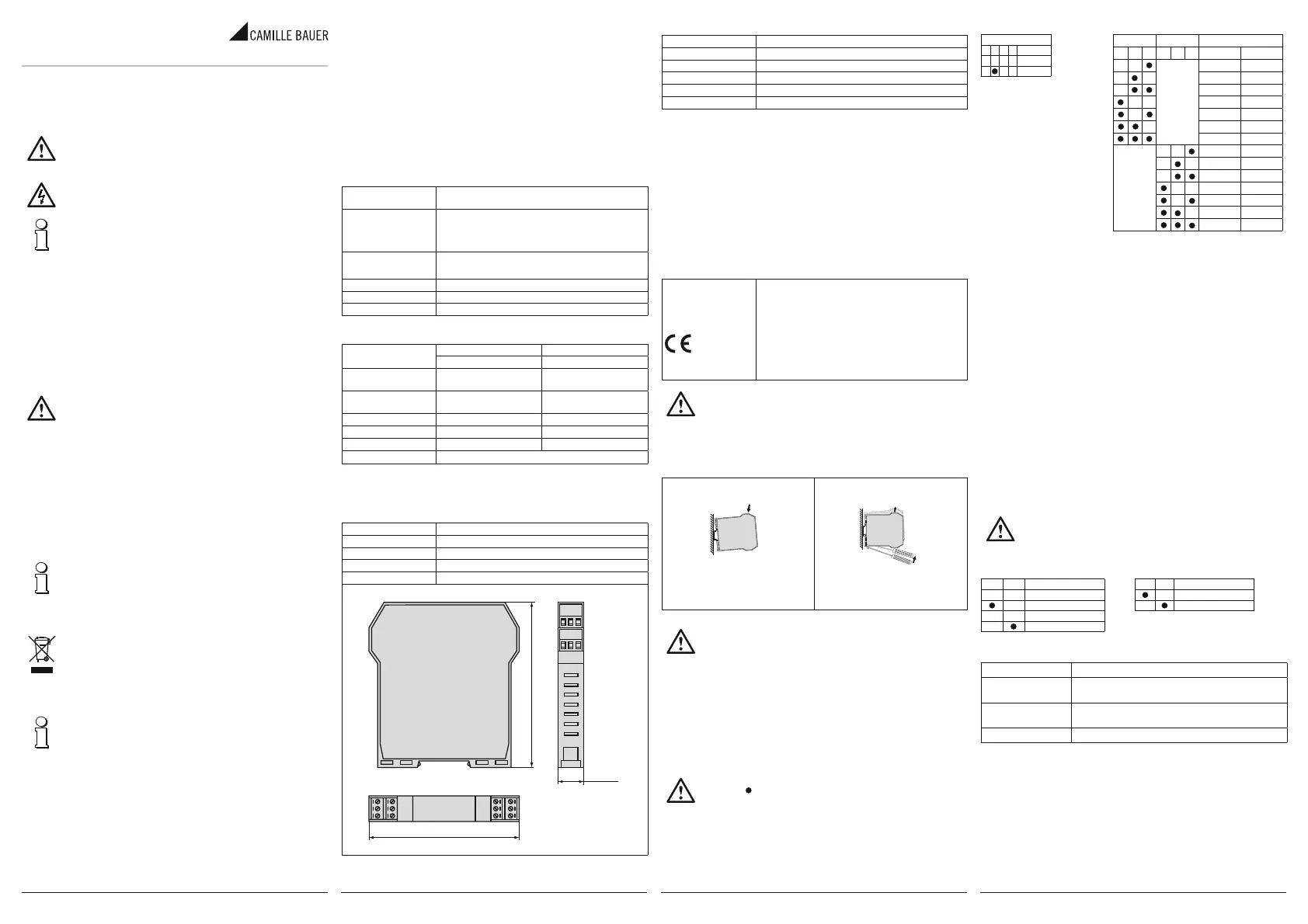
5. Mounting instructions
The signal converter is designed to be mounted on rails according to DIN 46277.
Mounting of signal converter
on the rail
1. Place the signal converter onto the top
part of the rail.
2. Press the signal converter downwards.
Removing the signal converter
from the rail
1. Use a screwdriver (as shown in the
fi gure) as a lever.
2. Turn the signal converter downwards.
For optimum function and longevity, ensure adequate ventilation of the signal.
We recommend installation in vertical position. Avoid installing the signal
converter above devices generating heat. We recommend installing it at the
bottom of the switch cabinet.
6. Installation instructions
6.1 Input selection
The input type is selected by setting the DIP switch group SW1.
Each input type corresponds to a certain number of scale start and end values which may be
selected by setting DIP switch group SW2.
The table below lists the possible START and END values according to the input type selected.
Note for all tables:
The symbol
indicates that the DIP switch is in ON position.
No entry means the DIP switch is in OFF position!
SW2: START / END
STARTENDType
123456VoltageCurrent
0 V0 mA
400 mV1 mA
1 V4 mA
2 V-1 mA
-5 V-5 mA
-10 V-10 mA
-20 V-20 mA
100 mV1 mA
200 mV2 mA
500 mV3 mA
1 V4 mA
5 V5 mA
10 V10 mA
20 V20 mA
3. General features
• Input: Voltage, current.
• Power supply of the sensor in 2-wire technology: 20 V DC stabilised, max. 20 mA protected
against short circuits.
• Measurement on galvanically isolated analog output with active/passive output for voltage
and current.
• Selection of input type, START-END, output mode (zero determination, scale reversal),
output type (mA or V) by means of DIP switch.
• Indication of available power supply, of scale exceedance or setup error on the front side
via LED.
• Galvanic 3-way isolation: Test voltage 1500 V AC.
4. Technical data
4.1 General
Power supply
10…40 V DC, 19…28 V AC, 50…60 Hz, max. 2,5 W; 1,6 W at 24 V
DC with output 20 mA
Input
Voltage: -20 … +20 V, input impedance 1 MΩ,
max. resolution 15 bit + sign
Current: -20 … +20 mA, input impedance ~50 Ω,
max. resolution 1 μA
Output
Voltage: 0…10 V / 2…10 V, minimum load 2 kΩ
Current: 0…20 / 4…20 mA, maximum load 600 Ω
Resolution1.25 mV for voltage output / 2.5 μA for current output
Sample rate240 sps at a resolution of 11 bit + sign
Response time35 ms at a resolution of 11 bit
4.2 Accuracy data
Reference conditions
Ambient temperature 25 °C
Power supply 24 V
Error in relation to maxi-
mum measuring range:
Voltage/current inputVoltage output (*1)
Basic accuracy
(at reference )
0.1 %0.3 %
Temperature infl uence0.01 % /°K0.01 % / °K
Linearisation error0.05 %0.01 %
OtherEMI (*2): < 1 %
Data memory EEPROM for all confi guration data; memory period >40 years
(*1) Values to be added to the errors relating to the input selected
(*2) EMI: Electromagnetic interference
4.3 Installation data
DesignTop-hat rail housing
MaterialPBT (black)
ConnectionsCoded, pluggable screw terminals 0.2...2.5 mm
2
Housing ingress protectionIP20
Weight200 g
Dimensions
100 mm
17,5 mm
112 mm
SW1: INPUT TYPES
Input types
1234
V
mA
Note: Set the DIP switches while
module is powered down. This avoids
electrostatic discharges which might
damage the module.
6.2 Free setting of START and END for measuring
The START and END keys allow the free setting of the start and end values of the scale within
the measuring range set by means of the DIP switches. This procedure requires a suitable signal
generator which is able to provide the desired end or start values of the scale.
The procedure is as follows:
1. Use the respective DIP switches to set the desired input type as well as START and END for the
measurement which contain the desired scale start and end value for the measurement.
2. Switch on power supply.
3. Attach a generator or calibrator for the signal to be measured or transmitted.
4. Set the generator to the desired scale start value.
5. Press the START key for at least 3 s. The green LED on the front panel will fl ash to indicate that
the value has been stored.
6. Repeat step 4 and 5 for the desired END value.
7. Remove power supply of the module and set the DIP switches of group SW2 for the setting of
START and END values to the OFF position.
Now the module is confi gured for the desired start and end value of the scale. To reprogram it,
also for other input types, simply repeat the entire process.
6.3 Output selection
DIP switches Nos. 7 and 8 of the SW2 group allow the setting of the respective output with or
without zero determination, and normal or reversed output. The DIP switch group SW3 lets you
select the output type.
Note: Set the DIP switches while module is powered down. This avoids electrostatic
discharges which might damage the module.
SW2: OUTPUT MODE SW3: OUTPUT TYPES
78Output type12Output
0…20 mA / 0…10 V
Voltage
4…20 mA / 2…10 VCurrent
Normal
Reversed
6.4 LED indications on the front panel
LED (green)Meaning
Fast fl ashing
(Freq.: 1 fl ash/s)
Outside measuring range or internal fault
Slow fl ashing
(Freq. = 2 fl ash./s)
DIP switch setting error
Continuously onIndicates presence of power supply
Product specificaties
| Merk: | Camille Bauer |
| Categorie: | Receiver |
| Model: | Sineax TV815 |
Heb je hulp nodig?
Als je hulp nodig hebt met Camille Bauer Sineax TV815 stel dan hieronder een vraag en andere gebruikers zullen je antwoorden
Handleiding Receiver Camille Bauer

2 Februari 2024
2 Februari 2024
2 Februari 2024
2 Februari 2024
2 Februari 2024
2 Februari 2024
2 Februari 2024
2 Februari 2024
2 Februari 2024
Handleiding Receiver
Nieuwste handleidingen voor Receiver
15 Juli 2026
15 Juli 2026
15 Juli 2026
15 Juli 2026
14 Juli 2026
14 Juli 2026
13 Juli 2026
13 Juli 2026
13 Juli 2026
13 Juli 2026