Camille Bauer Sineax TV819 Handleiding
Camille Bauer Receiver Sineax TV819
Bekijk gratis de handleiding van Camille Bauer Sineax TV819 (4 pagina’s), behorend tot de categorie Receiver. Deze gids werd als nuttig beoordeeld door 96 mensen en kreeg gemiddeld 4.4 sterren uit 4 reviews. Heb je een vraag over Camille Bauer Sineax TV819 of wil je andere gebruikers van dit product iets vragen? Stel een vraag
Pagina 1/4
1
Contents
1. Read fi rst and then … ..........................................................................1
2. Scope of supply ....................................................................................1
3. Brief description ....................................................................................1
4. Overview of the parts ............................................................................1
5. Technical data .......................................................................................2
6. Opening and closing the device ...........................................................2
7. Mounting ...............................................................................................2
8. Electrical connections ...........................................................................2
9. Confi guration ........................................................................................3
10. Commissioning .....................................................................................3
11. Maintenance .........................................................................................3
12. Releasing the isolating amplifi er ...........................................................3
13. Dimensional drawings ...........................................................................4
14. Declaration of conformity ......................................................................4
1. Read fi rst and then …
The proper and safe operation of the device assumes that
the Operating Instructions are read and the safety warnings
given in the various Sections
7. Mounting
8. Electrical connections
9. Confi guration
10. Commissioning
are observed.
The device should only be handled by appropriately trained personnel who
are familiar with it and authorised to work in electrical installations.
The instrument must only be opened to make the confi guration, as de-
scribed in Section “9. Confi guration”.
The guarantee is no longer valid if the instrument is further tampered
with.
2. Scope of supply (Fig. 1 and 2)
Isolating amplifi er
Order Code: Signifi cance of the 1st to 7th digits
DescriptionOrder Code
1.Mechanical design819 -
Housing with screw terminals,
not pluggable
3
Housing with screw terminals,
pluggable
9
2.Version / Power supply
Standard/Power supply 24 … 60 V DC, AC1
Standard/Power supply 85 … 230 V DC, AC2
3.Function
1 input max. 1000 V
1 electrically insulated output
1
4.Input signal
Input [V]9
Input [mA]Z
Isolating amplifi er
SINEAX TV 819
TV 819 Be 147 969-02 06.13
Camille Bauer LTD
Aargauerstrasse 7
CH-5610 Wohlen/Switzerland
Phone +41 56 618 21 11
Fax +41 56 618 21 21
info@camillebauer.com
www.camillebauer.com
Operating Instructions
The instruments must only be disposed of in the
correct way!
The following symbols in the Operating Instructions indicate safety
precautions which must be strictly observed:
DescriptionOrder Code
5.Output signal
Output [V]9
Output [mA]Z
6.Output characteristics
Standard (directly proportional,
0…Y/0,2Y…Y/-Y…0…+Y)
0
Inversely (proportional, Y…0/Y…0,2Y/+Y…0…–Y)1
7.Test certifi cate
Without test certifi cate0
With test certifi cate in GermanD
With test certifi cate in EnglishE
Y = Output circuit full-scale value
Fig. 1 Fig. 2
1 Operating Instructions in German, French and English
3. Brief description
The purpose of the isolating amplifi er SINEAX TV 819 is to electrically insulate
input and output signals, respectively to amplify and/or change the signal
level or type (current or voltage) of the input signals.
Any of the input and output standard ranges given in the Section “9. Con-
figuration” and the type of input and output variable (current or voltage) are
simply selected by positioning soldered jumpers. The fine adjustment is
accomplished using the potentiometers “Zero” and “Span”.
The isolating amplifiers that are supplied as preferred devices have the fol-
lowing basic confi guration:
– Measuring input:
– Measuring output:
4 … 20 mA
4 … 20 mA
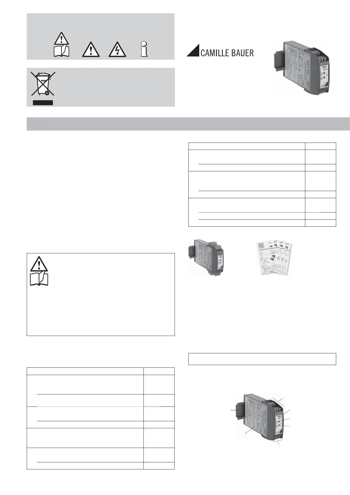
4. Overview of the parts
Figure 3 shows those parts of the device of consequence for electrical con-
nections and other operations described in the Operating Instructions.
ON
Zero
Span
(5)
(5)
(4)
(3)
Fig. 3
(3) Top-hat rail 35 × 15 mm or 35 × 7.5 mm (EN 50 022)
(4) Type label
(5) Screw terminals
ON Green LED for indicating device standing by
Product specificaties
| Merk: | Camille Bauer |
| Categorie: | Receiver |
| Model: | Sineax TV819 |
Heb je hulp nodig?
Als je hulp nodig hebt met Camille Bauer Sineax TV819 stel dan hieronder een vraag en andere gebruikers zullen je antwoorden
Handleiding Receiver Camille Bauer

2 Februari 2024
2 Februari 2024
2 Februari 2024
2 Februari 2024
2 Februari 2024
2 Februari 2024
2 Februari 2024
2 Februari 2024
2 Februari 2024
Handleiding Receiver
Nieuwste handleidingen voor Receiver
15 Juli 2026
15 Juli 2026
15 Juli 2026
15 Juli 2026
14 Juli 2026
14 Juli 2026
13 Juli 2026
13 Juli 2026
13 Juli 2026
13 Juli 2026