Camille Bauer Sineax TV809 Handleiding
Camille Bauer Receiver Sineax TV809
Bekijk gratis de handleiding van Camille Bauer Sineax TV809 (4 pagina’s), behorend tot de categorie Receiver. Deze gids werd als nuttig beoordeeld door 132 mensen en kreeg gemiddeld 4.5 sterren uit 5 reviews. Heb je een vraag over Camille Bauer Sineax TV809 of wil je andere gebruikers van dit product iets vragen? Stel een vraag
Pagina 1/4
1
Contents
1. Read fi rst and then … ...........................................................................1
2. Scope of supply ....................................................................................1
3. Brief description ....................................................................................1
4. Overview of the parts ............................................................................1
5. Technical data .......................................................................................2
6. Mounting ...............................................................................................2
7. Electrical connections ...........................................................................2
8. Confi guring the isolating amplifi er ........................................................3
9. Accessories and spare parts ................................................................3
10. Commissioning .....................................................................................3
11. Maintenance .........................................................................................3
12. Releasing the isolating amplifi er ...........................................................3
13. Dimensional drawings ...........................................................................4
14. Declaration of conformity ......................................................................4
1. Read fi rst and then …
The proper and safe operation of the device assumes that the
Operating Instructions are read and the safety warnings given
in the various Sections
6. Mounting
7. Electrical connections
8. Confi guring the isolating amplifi er
10. Commissioning
are observed.
Unauthorized repair or alteration of the unit invalidates the warranty!
The device should only be handled by appropriately trained personnel who
are familiar with it and authorised to work in electrical installations
.
2. Scope of supply (Fig. 1 and 2)
Isolating amplifi er
Order Code: Signifi cance of the 1st to 5th digits
DescriptionOrder Code
1.Mechanical design809 -
Housing with screw terminals, not pluggable3
Housing with screw terminals, pluggable9
2.Version/Power supply
Standard/Power supply 24 … 60 V DC, AC1
Standard/Power supply 85 … 230 V DC, AC2
[Ex ia Ga] IIC and [Ex ia Da] IIIC
Power supply 24 … 60 V DC, AC
3
[Ex ia Ga] IIC and [Ex ia Da] IIIC
Power supply 85…110 V DC/230 V AC
4
3.Current input rating
Input current max. fi nal value 100 mA (standard)1
Input current max. fi nal value 1.5 mA2
4.Alarm function
Without alarm function0
With built-in alarm relay1
Programmable
isolating amplifi er
SINEAX TV809
TV809 Be 147 802-04 08.12
Camille Bauer LTD
Aargauerstrasse 7
CH-5610 Wohlen/Switzerland
Phone +41 56 618 21 11
Fax +41 56 618 35 35
info@camillebauer.com
www.camillebauer.com
Operating Instructions
The instruments must only be disposed of in the
correct way!
The following symbols in the Operating Instructions indicate safety
precautions which must be strictly observed:
DescriptionOrder Code
5.Test records
Without test records0
With test records in GermanD
With test records in EnglishE
Fig. 1 Fig. 2
1 Operating Instructions (2) each in German, French and English
1 Ex approval (3), only for Ex version devices
3. Brief description
The purpose of the isolating amplifi er SINEAX TV809 is to electrically insulate
input and output signals, respectively to amplify and/or change the signal
level or type (current or voltage) of the input signals.
An explosion-proof “intrinsically safe” [Ex ia Ga] IIC and [Ex ia Da] IIIC version
rounds off this series of SINEAX TV809.
Measured variables and measuring ranges are programmed with the aid of a
PC, a programming cable and the programming software. Specifi c measured
variable data such as output signal, transmission characteristics and various
functions in combination with the alarm function can also be programmed.
Isolating amplifi er supplied as standard versions are confi gured as follows:
– Measuring input:
– Measuring output:
– Response time:
– Mains ripple suppression:
4 … 20 mA
4 … 20 mA
80 ms
50 Hz
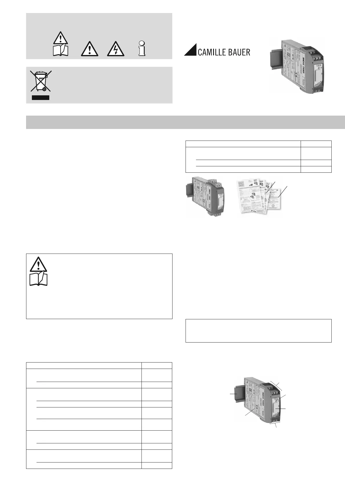
4. Overview of the parts
Figure 3 shows those parts of the device of consequence for electrical con-
nections and other operations described in the Operating Instructions.
(6)
ON
(7)
(6)
(5)
(4)
Fig. 3
(4) Top-hat rail 35 × 15 mm or 35 × 7.5 mm (EN 50022)
(5) Type label
(6) Terminals
ON Green LED to indicate the operating state and limit exceeded. The LED fl ashes
(option)
(7) Programming connector
(2)
(3)
Product specificaties
| Merk: | Camille Bauer |
| Categorie: | Receiver |
| Model: | Sineax TV809 |
Heb je hulp nodig?
Als je hulp nodig hebt met Camille Bauer Sineax TV809 stel dan hieronder een vraag en andere gebruikers zullen je antwoorden
Handleiding Receiver Camille Bauer

2 Februari 2024
2 Februari 2024
2 Februari 2024
2 Februari 2024
2 Februari 2024
2 Februari 2024
2 Februari 2024
2 Februari 2024
2 Februari 2024
Handleiding Receiver
Nieuwste handleidingen voor Receiver
15 Juli 2026
15 Juli 2026
15 Juli 2026
15 Juli 2026
14 Juli 2026
14 Juli 2026
13 Juli 2026
13 Juli 2026
13 Juli 2026
13 Juli 2026