Tempo PA1594 Handleiding
Bekijk gratis de handleiding van Tempo PA1594 (3 pagina’s), behorend tot de categorie Kabels voor pc's en randapparatuur. Deze gids werd als nuttig beoordeeld door 70 mensen en kreeg gemiddeld 4.4 sterren uit 35.5 reviews. Heb je een vraag over Tempo PA1594 of wil je andere gebruikers van dit product iets vragen? Stel een vraag
Pagina 1/3

INSTRUCTION MANUAL
MANUAL DE INSTRUCCIONES / MANUEL D’INSTRUCTIONS
Read understand and all of the instructions and safety information in this
manual before operating or servicing this tool.
Lea entienda y todas las instrucciones y la información de seguridad de este
manual antes de utilizar o de reparar la máquina.
Veuillez et vous assurer de bien toutes les instructions et les lire comprendre
informations relatives à la sécurité présentées dans ce manuel avant d’utiliser cet
appareil ou de procéder à son entretien.
52082061 REV 1 © 2019 Tempo Communications Inc. 11/19
PA1594
LAN and A/V Cable-Check™ Tester
Medidor de LAN y A/V Cable-Check™
Testeur LAN et AV Cable-Check™
English 2 ..................
Español 4 .................
Français 6 ................

PA1594
TEMPO COMMUNICATIONS 1390 Aspen Way • Vista, Ca 92081 USA • 800-642-2155
2
Description
The PA1594 LAN and A/V Cable-Check™ Tester is a small, hand-held cable
tester that enables network professionals to quickly and easily verify the integrity
of straight-through, twisted pair, and coaxial cables. The PA1594 can also test
crossover cable.
Safety
Safety is essential in the use and maintenance of Tempo tools and equipment. This
instruction manual and any markings on the tool provide information for avoiding
hazards and unsafe practices related to the use of this tool. Observe all of the safety
information provided.
Purpose of this Manual
This manual is intended to familiarize all personnel with the safe operation and
maintenance procedures for the Tempo Communications PA1594.
Keep this manual available to all personnel. Replacement manuals are available upon
request at no charge at www.TempoCom.com.
Important Safety Information
Electric shock hazard:
• Before using the tester, disconnect the cable to be tested from
any device.
• Contact with live circuits could result in severe injury or death.
Features
• Tests UTP (Unshielded Twisted Pair), STP (Shielded Twisted Pair), and coaxial cable.
• Checks continuity and configuration of wiring with RJ45 plugs.
• Tests for open circuits, shorts, miswires, reversals, and split pairs.
• Shield detection tests a cable’s shield integrity.
• Debug mode quickly identifies which cable pairs have a specific wiring fault.
• Main unit and Remote unit allow one person to test T568A, T568B, 10Base-T, and
Token Ring cables.
• Main unit is powered by two 1.5 V (AAA) batteries; Remote unit does not need
battery.
• Low battery indication.
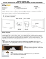
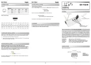
Setup
To separate the two units, hold
the Main unit in one hand and
the Remote unit in the other.
Slide the Remote unit up or
down.
Slide the
Remote unit
up or down.
Remote Unit
Main Unit
Identification
Main Unit Remote Unit
Pair and SHIELD LEDs:
1. SHIELD/COAX LED
2. Pair 1-2 LED
3. Pair 3-6 LED
4. Pair 4-5 LED
5. Pair 7-8 LED
Fault Indicator LEDs:
6. SHORT LED
7. MISWIRE LED
8. SPLIT PAIR LED
9. REVERSAL LED
Others:
10. LOW BATT LED
11. Mode selector switch
12. TEST button
13. BNC socket of Main unit
14. RJ45 socket of Main unit
15. RJ45 socket of Remote unit
16. BNC socket of Remote unit
Typical Faults
For straight-through cable or crossover cable tests, the tester has two operating
modes: Test mode and Debug mode.
In Test mode, a flashing pair of LEDs indicates that this wire pair has a fault while a
fault indicator LED lights up to indicate which fault was detected. Multiple flashing
pair LEDs indicate multiple pairs and/or multiple faults. In this situation, use the
Debug mode to diagnose the faults in more detail. Correct the faults until the cable is
verified to be correct by using the tester.
Refer to the “Fault Details” section on the last page of this manual.
Note: For some types of cables, so called OPEN is not an abnormal condition.
Therefore, there is no OPEN indicator LED. Open can be identified as an unlit pair or
shield LED when the tester shows the test result. The user should determine if a wire
is present and continuous or OPEN by comparing the illuminated pair and/or shield
LEDs with the expected number of wires (of the cable) that should be good.
During test, if the LOW BATT LED lights up, the batteries in the Main unit are low. To
avoid questionable test results, replace the batteries immediately.
Do not discard this product or throw away!
For recycling information, go to www.TempoCom.com.
All specifications are nominal and may change as design improvements occur. Tempo
Communications Inc. shall not be liable for damages resulting from misapplication or misuse of
its products.
Cable-Check is a trademark of Tempo Communications Inc.
KEEP THIS MANUAL

PA1594
3
TEMPO COMMUNICATIONS 1390 Aspen Way • Vista, Ca 92081 USA • 800-642-2155
Testing a Straight-through Cable
Test Mode
1. Connect the Main unit to one end of the cable to be tested and the Remote unit
to the other end of this cable.
2. Set the mode selector switch to the position.Standard
3. Press the button and then release it. The tester starts testing the cable. TEST
The five green LEDs flash one time sequentially from top to bottom, and then the
tester shows the test result—flashing LED indicates this pair has a fault while
fault indicator LED lights up to indicate the type of fault.
4. The test lasts about 12 seconds, and then the tester turns off automatically.
Press the button to stop the test manually at any time. Pressing the TEST TEST
button turns the tester off.
Example for Test mode: The cable fault is a SHORT on pair 1-2 and pair 3-6.
After the five green LEDs flash one time sequentially from top to bottom, the tester
displays the following test results simultaneously:
• Pair 1-2 LED and pair 3-6 LED flash green while the SHORT LED lights red.
• Pair 4-5 LED lights green indicating a good pair.
• Pair 7-8 LED lights green indicating a good pair.
Debug Mode
The Debug mode identifies which cable pairs have a wiring fault. The unit cycles
through pairs, displaying a test result one pair at a time. A fault is indicated by
simultaneously lighting a pair of LEDs and the fault indicator.
1. Set the mode selector switch to the position. Then press and hold the Standard
TEST button until all LEDs light; release the button.
2. The pair LEDs and the fault indicator LEDs work together to identify which pair is
incorrect.
a. If a pair LED flashes two times in series (one short and one long) while no
fault indicator LED lights, the pair is wired correctly.
b. If a pair has fault(s), its pair LED will give a short flash. Then this pair LED,
other pair LEDs related to this pair’s fault(s), and the fault indicator LED(s) will
give a long flash simultaneously.
c. If a pair LED gives only a short flash that is not followed by a long flash, this
pair has an OPEN fault.
3. After the Debug function cycles four times through the pairs, the tester turns
off automatically. Press the button to stop the test manually at any time. TEST
Pressing the button turns the tester off.TEST
Example for Debug mode: The cable fault is a SHORT on pair 1-2 and pair 3-6.
The Debug mode LED series will be as follows:
• Pair 1-2 LED gives a short flash and then pair 1-2 LED, pair 3-6 LED, and the
SHORT red LED give a long flash simultaneously.
• Pair 3-6 LED gives a short flash and then pair 3-6 LED, pair 1-2 LED, and the
SHORT red LED give a long flash simultaneously.
• Pair 4-5 LED flashes two times in series while no fault indicator LED lights. This
indicates that this pair is wired correctly.
• Pair 7-8 LED flashes two times in series while no fault indicator LED lights. This
indicates that this pair is wired correctly.
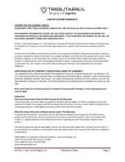
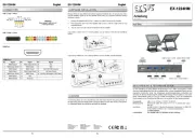
Testing a Crossover Cable
The method of testing crossover cable is almost the same as testing straight-through
cable. The only difference is that the mode selector switch is in position Cross Cable
to test crossover cable instead of the position for straight-through cable.Standard
Refer to the “Testing a Straight-through Cable” section and set the mode selector
switch to the position to test crossover cable.Cross Cable
1
2
3
4
5
6
7
8
1
2
3
4
5
6
7
8
Crossover Cable Wiring
Testing Coaxial Cable
Note: For coaxial cable tests, the mode selector switch can be in any function
position.
1. Connect one end of the coaxial cable to be tested to the BNC socket of the Main
unit and the other end of the coaxial cable to the BNC socket of the Remote unit.
Note: The terminators on the cable to be tested should match the BNC sockets
of the tester.
2. Press the button and then release it. The five green LEDs of the Main unit TEST
will flash one time sequentially from top to bottom, and then the tester shows the
test result:
• If the SHIELD/COAX LED lights green, the coaxial cable has no fault.
• If the SHIELD/COAX LED does not light, the cable is faulty.
Note: Refer to “Testing Examples” on the last page of this manual for reference on
how to test the continuity of RCA, BNC, and Cable TV “F” cables.
Indicator Light
Illuminated Result Resistance
PASS Good continuity 40-100 Ω
SHORT Cable is shorted < 40 Ω
OPEN Cable is broken, bad shield connector, or
bad center conductor connection > 100 Ω
Specifications
Cable Length:
Minimum: 1 m (3 ft)
Maximum: 300 m (900 ft)
Battery: 2 x 1.5 V AAA
Size:
Master Unit: 96.8 x 58.2 x 32.8 mm (3.81 x 2.29 x 1.29 in)
Remote Unit: 96.8 x 58.2 x 32.8 mm (3.81 x 2.29 x 1.29 in)
Weight: Approximately 165 g (5.8 oz)
Maintenance
Battery Replacement
When the LOW BATT LED lights continuously, the batteries are low and should be
replaced immediately.
1. Remove the screws on the back cover of the Main unit and remove the back
cover.
2. Replace the old batteries with new ones (observe polarity).
3. Reinstall the back cover and the screws.
Product specificaties
| Merk: | Tempo |
| Categorie: | Kabels voor pc's en randapparatuur |
| Model: | PA1594 |
| Ingebouwd display: | Nee |
| Land van herkomst: | China |
| Ondersteund aantal accu's/batterijen: | 2 |
| Type product: | Tester voor kabels met getwiste aderparen |
| Type batterij: | AAA |
| Testtype: | Kruisverbinding testen |
| Ondersteunde aansluitingen: | RJ-11, RJ-45 |
| Maximum kabellengte: | 500 m |
Heb je hulp nodig?
Als je hulp nodig hebt met Tempo PA1594 stel dan hieronder een vraag en andere gebruikers zullen je antwoorden
Handleiding Kabels voor pc's en randapparatuur Tempo

31 Januari 2024

31 Januari 2024

31 Januari 2024
Handleiding Kabels voor pc's en randapparatuur
- NZXT
- Atlona
- Akasa
- Luxul
- Duronic
- DataComm
- AudioQuest
- Xiaomi
- Worx
- Apple
- Abus
- Goobay
- Greenlee
- Extron
- Savio
Nieuwste handleidingen voor Kabels voor pc's en randapparatuur
5 Augustus 2025
5 Augustus 2025

5 Augustus 2025

4 Augustus 2025
29 Juli 2025
29 Juli 2025
28 Juli 2025
26 Juli 2025
25 Juli 2025
21 Juli 2025