Seco-Larm E-936-S45RRGQ Handleiding
Seco-Larm Niet gecategoriseerd E-936-S45RRGQ
Bekijk gratis de handleiding van Seco-Larm E-936-S45RRGQ (4 pagina’s), behorend tot de categorie Niet gecategoriseerd. Deze gids werd als nuttig beoordeeld door 63 mensen en kreeg gemiddeld 4.6 sterren uit 6 reviews. Heb je een vraag over Seco-Larm E-936-S45RRGQ of wil je andere gebruikers van dit product iets vragen? Stel een vraag
Pagina 1/4
Conforms to UL 325
Caution:
This sensor was not designed to prevent bodily injury or loss of life.
This sensor was not designed for use in environments where explosive gases may be present.
Use of this sensor in certain security applications may be regulated by local laws or codes. SECO-LARM
is not responsible for compliance with such laws or codes.
Features:
Range 45 ft (14m)
Weatherproof (IP66) construction for
indoor/outdoor usage
Pre-wired 6.5ft (2m) cord
Bracket and mounting hardware included
for both sensor and reflector
Adjustable sensing range
Compact size
Typical Applications:
Sensor for garage doors or outdoor gates
Entry detection for store fronts
Assist in measuring parking distance
Light on type
IMPORTANT: The E-936-S45RRGQ
conforms to UL325 for gate operators that
use the N.C. or 10kΩ resistor for
monitoring.
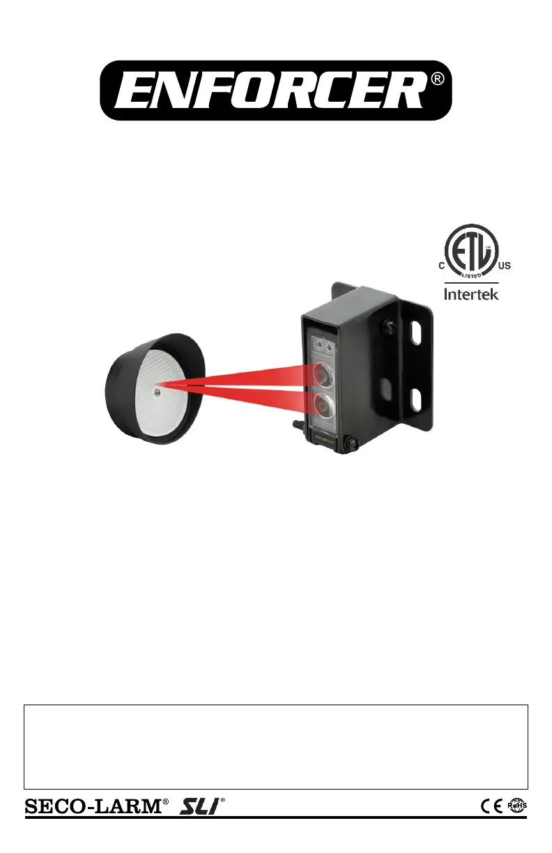
E-936-S45RRGQ
Retro-Reflective Photoelectric Beam Sensor
Manual
Product specificaties
| Merk: | Seco-Larm |
| Categorie: | Niet gecategoriseerd |
| Model: | E-936-S45RRGQ |
| Kleur van het product: | Zwart |
| Breedte: | 20.5 mm |
| Diepte: | 39 mm |
| Hoogte: | 63 mm |
| Internationale veiligheidscode (IP): | IP66 |
| Certificering: | CE, RoHS |
| Responstijd: | 10 ms |
| Spanning: | 12 V |
| Omgevingstemperatuur (min): | -20 °C |
| Omgevingstemperatuur (max): | 55 °C |
| AC-ingangsfrequentie: | 60 Hz |
| Lichtbron: | IR LED |
| Stroom (max.): | 0.07 A |
| Alarmafstand: | 14 m |
Heb je hulp nodig?
Als je hulp nodig hebt met Seco-Larm E-936-S45RRGQ stel dan hieronder een vraag en andere gebruikers zullen je antwoorden
Handleiding Niet gecategoriseerd Seco-Larm

8 Februari 2024
2 Februari 2024
2 Februari 2024
2 Februari 2024
2 Februari 2024
2 Februari 2024
2 Februari 2024
2 Februari 2024
2 Februari 2024
2 Februari 2024
Handleiding Niet gecategoriseerd
Nieuwste handleidingen voor Niet gecategoriseerd
23 Juli 2026
23 Juli 2026
23 Juli 2026
22 Juli 2026
22 Juli 2026
22 Juli 2026
22 Juli 2026
22 Juli 2026
22 Juli 2026
21 Juli 2026