Seco-Larm SD-6276-SSVQ Handleiding


Lees hieronder de 📖 handleiding in het Nederlandse voor Seco-Larm SD-6276-SSVQ (4 pagina's) in de categorie Niet gecategoriseerd. Deze handleiding was nuttig voor 12 personen en werd door 2 gebruikers gemiddeld met 4.5 sterren beoordeeld

Pagina 1/4
®
Outdoor Piezoelectric
Request-to-Exit Pushbuttons
Manual
Features:
ï‚· Piezoelectric push buttons for indoor or
outdoor use (IP65)
ï‚· LED ring around button changes from
green to red or red to green when the
button is pressed
ï‚· Timed or toggle output
ï‚· Includes separate manual override button
in case power to piezoelectric push button
fails
ï‚· Relay rated 5A@24VDC with two
individually programmable outputs
(NO/NC)
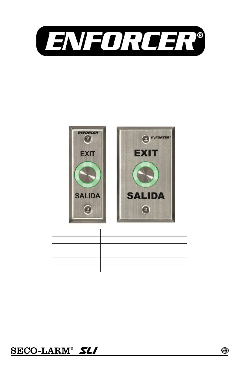
SD-6176-SSQ Slimline plate "TOUCH/EXIT"
SD-6176-SS1Q Slimline plate "EXIT/SALIDA"
SD-6176-SSVQ Slimline plate, manual override
SD-6276-SSQ Single-Gang plate, "TOUCH/EXIT"
SD-6276-SS1Q Single-Gang plate, "EXIT/SALIDA"
SD-6276-SSVQ Single-Gang plate, manual override
ENFORCER Outdoor Piezoelectric Request-to-Exit Pushbuttons
2 SECO-LARM U.S.A., Inc.
1x Piezoelectric push button 2x Wires for manual override
1x Manual 2x Mounting screws
Operating voltage 12~24VDC
Contact rating 2.5A@24 VAC/VDC
Ring
LED
Standby Red
Active Green
Output time 1~30s, Toggle
IP rating IP65
Operating temperature 32°~158° F (0°~70° C)
Plate material Stainless steel
Weight
Single-Gang 3.5-oz (99g)
Single-Gang w/ manual override 4-oz (113g)
Slimline 2.6-oz (74g)
Slimline w/ manual override 3.1-oz (88g)
Overview:
Introduction:
Parts List:
Installation:
*SD-6176-SSVQ and SD-6276-SSVQ with Manual Override button shown, other models similar.
Slimline Single-Gang Side View Rear View
*SD-6176-SSVQ and SD-6276-SSVQ only.
1. Prepare wiring to provide 12~24 VDC power and connect devices to the relay outputs.
NOTE: The device includes one relay with two outputs. Outputs trigger simultaneously but can be configured
independently. To set the output modes, see Relay Output Modes on page 3.
2. Remove the plastic cover from the rear of the switch and carefully pierce the rubber grommet.
3. SD-6176-SSVQ and SD-6276-SSVQ: Wire the manual override button. See page 3.
4. Wire the switch according to the diagram on the right.
5. Connect (-) and (+) to a 12~24 VDC power source.
6. Connect other devices to Output 1 or 2.
7. Replace the plastic switch cover and screw the plate
onto the mounting surface
Te
r
minal Block
LED Rin
g
Piezoelectric
pushbutton
Manual
Override
Button*
Manual
Override
Button*
Timer
Adjustment
Output mode
Selection
LED color
Selection
Terminal
blocks
Relay adjust
Buzzer
adjust
(Plastic switch
cover removed)
15/8" (42mm)
15
/8" (42mm) 23/4" (70mm)
41/2"
(114mm
)
ENFORCER Outdoor Piezoelectric Request-to-Exit Pushbuttons
SECO-LARM U.S.A., Inc. 3
Wiring the Manual Override: SD-6176-SSVQ and SD-6276-SSVQ Only
Configuring the Pushbutton:
Connect the manual override button with included wires
Wiring for N.O.:
Connect the two
wires between the
NO and COM
terminals of the
override button and
the Output 1 or 2
terminals on the
switch.
Wiring for N.C.:
Connect the two
wires between
the NC and COM
terminals of the
override button
and the Output 1
or 2 terminals on
the switch.
COM
N.O.
COM
N.C.
Notes:
1. Remove the thin panel on the bottom of the plastic cover to allow wiring to pass through.
2. There is only one relay, wiring the button to either output will allow the other output to trigger simultaneously.
3. Do not connect the manual override button to more than one output.
4. When wiring for either N.O. or N.C., be sure to also set the Relay Output Mode to N.O., as described below.
If Relay Output Mode and override button wiring do not match, the product may not function as expected
Manual
Override Button
1. Buzzer Output
2. Relay Output Mode
3. LED Ring Colors
4. Switch Output Type
5. Time Adjustment
Default:ON
Use the buzzer output jumper JP3 to program the buzzer output.
Placing the jumper on the left turns buzzer output ON. Placing the
j
umper on the right turns buzzer outputs OFF.
Outputs 1 and 2 can be set independently using jumpers JP1 and JP2.
Note: Both outputs trigger simultaneously. Place the jumper on the right
for N.O. operation and on the left for N.C. operation
Default: N.O
ON: LED is green while in standby, and turns red when triggered.
OFF: LED is red while in standby, and turns green when triggered.
Default: OFF
TIMER: When set to TIMER, pressing the switch will trigger the relay
for the set time. Set the time using the trimpot as described above.
TOGGLE: When set to TOGGLE, pressing the switch will cause the
relay to trigger until the switch is pressed
Default: Timer
Output duration is adjustable 1~30 seconds. (Must be set to ‘Timer’ in step 4)
Gently rotate the trimpot using a Philips head screwdriver.
Counterclockwise decreases the output time.
Clockwise increases the output time.
Default: 1s


Product specificaties

Merk: Seco-Larm
Categorie: Niet gecategoriseerd
Model: SD-6276-SSVQ
Kleur van het product: Roestvrijstaal
Breedte: 70 mm
Diepte: 42 mm
Hoogte: 114 mm
Materiaal behuizing: Roestvrijstaal
Internationale veiligheidscode (IP): IP65
Connectiviteitstechnologie: Bedraad
Type stroombron: DC
Kleur licht: Green, Red
Stroomverbruik: 100 mA
DC voltage bereik: 12 - 24 V
Bedrijfstemperatuur (T-T): 0 - 70 °C
Verlichting: Ja

Heb je hulp nodig?

Als je hulp nodig hebt met Seco-Larm SD-6276-SSVQ stel dan hieronder een vraag en andere gebruikers zullen je antwoorden


Handleiding Niet gecategoriseerd Seco-Larm

Handleiding Niet gecategoriseerd

Nieuwste handleidingen voor Niet gecategoriseerd