Seco-Larm SA-025Q Handleiding
Seco-Larm Niet gecategoriseerd SA-025Q
Bekijk gratis de handleiding van Seco-Larm SA-025Q (2 pagina’s), behorend tot de categorie Niet gecategoriseerd. Deze gids werd als nuttig beoordeeld door 53 mensen en kreeg gemiddeld 4.3 sterren uit 3 reviews. Heb je een vraag over Seco-Larm SA-025Q of wil je andere gebruikers van dit product iets vragen? Stel een vraag
Pagina 1/2
- 1 -
The SA-025Q Programmable Timer Module is suitable for a wide range of timed security
and access control operations, such as door unlock timing, siren or bell timer, VCR timer,
and so on. Auto-sensing of input voltage and DIP switches for programming make
installation easy.
Features / Specifications:
•Timer can be set from 1 second to 60 minutes
•Can be triggered via a N.O. positive (+) trigger input signal or a N.C. negative (-) trigger
device or by powering up the unit
•Relay can be programmed to activate at the start or at the end of the timing cycle
•Relay can also be set to activate for one second at the end of the timing cycle
•Relay can be programmed to pulse (flash) or be steady on
•Built-in reset function to manually reset timing cycle
•Form-C relay, contacts rated 8A @ 120VAC/24VDC
•LED indicates relay is energized
•12VDC/24VDC operation (auto sensing)
•Current draw – Less than 1mA (standby) or 50mA (relay energized)
•Board measures 2-7/8” x 2-1/2” (73 x 63 mm)
•Functions programmed via DIP switches – no jumpers to cut
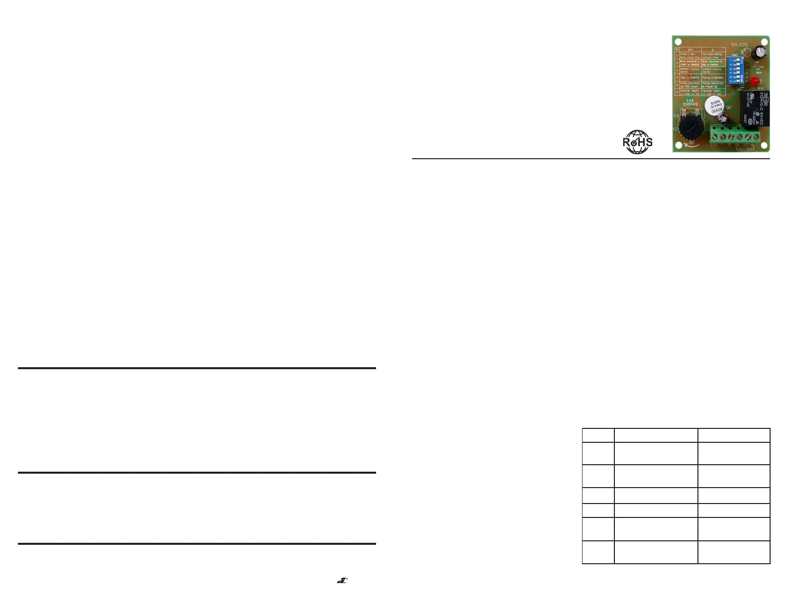
Fig. 1 – DIP switch settings
Switch
#1
#2
#3
#4
#5
#6
Off
Fixed 1 sec. Relay
output time
Relay energizes at start
of timing cycle
REPEAT timing cycle
Time in MINUTES
Timing controlled by
TRG input
Counter begin at START
of TRG
On
Variable Relay output
time
Relay energizes at
end of timing cycle
SINGLE timing cycle
Timing in SECONDS
Timing controlled by
Power Up
Counter begin at END
of TRG
ENFORCER
®
Installation Manual
SA-025Q
Programmable Timer Module
Wiring:
•TRG –N.O. Positive (+) trigger input
signal or
–N.C. Negative (
-
) trigger input
signal
(1K ohm resistor
required - included)
•(-) – Ground input
•(+) – +12VDC to +24VDC input
•NO – Relay output (normally open)
•COM – Relay output (common)
•NC – Relay output (normally closed)
DIP Switch Settings (Programming):
The SA-025Q is programmed via a
series of six DIP switches which can be
turned on or off. See fig. 1.
b.Action – If the TRG terminal is connected to (+) for the time set by the timer, the
relay activates and remains activated. To reset the latched relay, connect the TRG
terminal momentarily to (+) again.
c.Triggering by powering unit up – If DIP switch #5 is set to ON, the delay period set
by the timer starts when the SA-025Q is powered up. At the end of the delay period,
the relay latches on and remains on until the SA-025Q is disconnected from power.
5.Pulsing or Flashing Output, instant or delay (Fig. 6):
a.DIP switch settings:
1 – Relay output mode, see below
2 – Instant/delay start, see below
3 – OFF
4 – Timer setting (ON or OFF)
5 – OFF
6 – OFF
b.Action – If the TRG terminal is connected to (+) momentarily, the SA-025Q waits for
the time set by the timer, and then starts pulsing/flashing. The pulse/flash output lasts
until the TRG terminal is disconnected from (+).
c.Triggering by powering unit up – If DIP switch #5 is set to ON, the output works the
same, but instead of triggering via the TRG terminal, the SA-025Q is triggered by
being powering up.
d.Instant/delay start – If DIP switch #2 is set to ON, the SA-025Q waits for the time set
by the timer after triggered or powered up, and then starts pulsing/flashing. If DIP
switch #2 is set to OFF, the SA-025Q starts pulsing/flashing as soon as it is triggered
or powered up.
e.Relay output time – If DIP switch #1 is set to ON, the relay on and off time depends
on how the timer is set. If DIP switch #1 is set to OFF, the relay on time is fixed at
about 1 second, and the relay off time depends on how the timer is set.
6.Optional Negative Trigger or Closed-Circuit Trigger (Fig. 7):
If a closed-circuit negative trigger is required, it is necessary to install a 1K
(1,000-ohm) resistor as shown (included).
Note: Products with model number that ends with "Q" or have a green “Q” sticker represents RoHS compliant products.
WARRANTY:
This SECO-LARM product is warranted against defects in material and workmanship while used in normal
service for a period of one (1) year from the date of sale to the original consumer customer. SECO-LARM’s obligation is
limited to the repair or replacement of any defective part if the unit is returned, transportation prepaid, to SECO-LARM.
This Warranty is void if damage is caused by or attributed to acts of God, physical or electrical misuse or abuse, neglect,
repair, or alteration, improper or abnormal usage, or faulty installation, or if for any other reason SECO-LARM determines that
such equipment is not operating properly as a result of causes other than defects in material and workmanship.
The sole obligation of SECO-LARM, and the purchaser’s exclusive remedy, shall be limited to replacement or repair only, at
SECO-LARM’s option. In no event shall SECO-LARM be liable for any special, collateral, incidental, or consequential personal
or property damages of any kind to the purchaser or anyone else.
NOTICE:
The information and specifications printed in this manual are current at the time of publication.
However, the SECO-LARM policy is one of continual development and improvement. For this reason, SECO-LARM
reserves the right to change specifications without notice. SECO-LARM is also not responsible for misprints or
typographical errors.
Copyright © 2007 SECO-LARM U.S.A., Inc. All rights reserved. This material may not be reproduced or copied, in
whole or in part, without the written permission of SECO-LARM.
SECO-LARMSECO-LARM
SECO-LARMSECO-LARM
SECO-LARM
®
U.S.A., Inc. U.S.A., Inc.
U.S.A., Inc. U.S.A., Inc.
U.S.A., Inc.
16842 Millikan Avenue, Irvine, CA 92606
Tel: 800-662-0800 / 949-261-2999 Fax: 949-261-7326
Website: www.seco-larm.com
E-mail: sales
@
seco-larm.com
file: D/DTP/MISA-025Q_074
MIA025.P65/FEB2003
Order Part #760-100-3/074
PITSW1
Product specificaties
| Merk: | Seco-Larm |
| Categorie: | Niet gecategoriseerd |
| Model: | SA-025Q |
Heb je hulp nodig?
Als je hulp nodig hebt met Seco-Larm SA-025Q stel dan hieronder een vraag en andere gebruikers zullen je antwoorden
Handleiding Niet gecategoriseerd Seco-Larm

8 Februari 2024
2 Februari 2024
2 Februari 2024
2 Februari 2024
2 Februari 2024
2 Februari 2024
2 Februari 2024
2 Februari 2024
2 Februari 2024
2 Februari 2024
Handleiding Niet gecategoriseerd
Nieuwste handleidingen voor Niet gecategoriseerd
23 Juli 2026
23 Juli 2026
23 Juli 2026
23 Juli 2026
23 Juli 2026
22 Juli 2026
22 Juli 2026
22 Juli 2026
22 Juli 2026
22 Juli 2026