Sanwa MG1000 Handleiding
Sanwa Meetapparatuur MG1000
Bekijk gratis de handleiding van Sanwa MG1000 (2 pagina’s), behorend tot de categorie Meetapparatuur. Deze gids werd als nuttig beoordeeld door 228 mensen en kreeg gemiddeld 4.8 sterren uit 3 reviews. Heb je een vraag over Sanwa MG1000 of wil je andere gebruikers van dit product iets vragen? Stel een vraag
Pagina 1/2
07-1409 2040 6012
[1] SAFETY PRECAUTIONS
Before use, read the following safety precautions.
Thank you for purchasing the Sanwa MG1000/MG500 digital insulation
resistance tester. Before use, please read this manual thoroughly to ensure
correct and safe use. Keep this Instruction Manual together with the product.
Be sure to read the information under “ WARNING” that is intended to prevent
personal injury such as burn and electric shock and other serious accidents.
1-1 Explanation of Warning Symbols
The meaning of the symbols used in this manual and attached to the product is
as follows:
: Very important instructions for safe use
•
The warning messages are intended to prevent accidents to operating
personnel such as burn and electric shock.
•
The caution messages are intended to prevent incorrect handling and
measurement which may damage the product.
: Dangerous voltages
: Ground. : DC. : AC.
: Fuse. : Double or enhanced insulation.
1-2 Warning Messages for Safe Use
WARNING
The following instructions are intended to prevent personal injury such as burn and
electric shock. Be sure to follow them when using the tester:
1-3 Overload protection
The maximum rated input value and overload protection have been defined for
the input terminals of each function as shown below.
Function Max. Rated Input Overload Protection
MΩ -
M
Ω
range: Within 120 % of the rated measuring voltage.
V 600 Vrms 780 Vrms
4000 Ω- 600 Vrms
40 Ω- Fuse, 0.5 A / 600 V
Measurement Category (Overvoltage Category)
Overvoltage measurement category II (CAT. II ) :
Line on the primary side of equipment with power cord to be connected to the
receptacle.
Overvoltage measurement category III (CAT. III ) :
Line from the primary side or branch of equipment which directly takes in
electricity from a distribution board to the receptacle.
Overvoltage measurement category IV (CAT. IV ) :
Line from the service conductor to the distribution board.
[2] APPLICATIONS AND FEATURES
2-1 Applications
This instrument is a DC insulation resistance tester for use in measurement of
insulation resistance of a power line and power equipment within the range of
600 V under CAT III.
2-2 Features
•
Safety design in compliance with IEC61010-1
•
MΩ function with automatic live circuit detection (>30 V AC/DC)
•
Easy-to-read display showing large figures and log bar graph for reading in an
analog feeling
•
Automatic hold function to hold the last displayed value to look it safely after
measurement
•
LCD panel with backlight function
•
Auto discharge function
•
40.00 Ω measurement function (≧200 mA short circuit current)
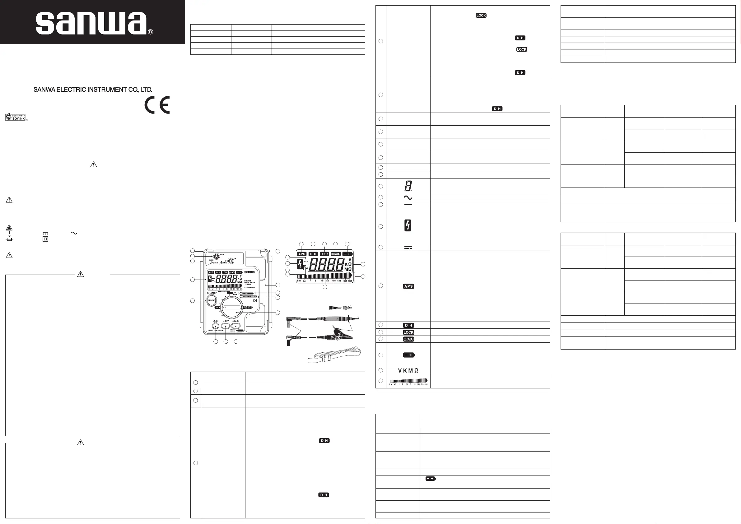
[3] NAMES AND FUNCTIONS OF COMPONENT UNITS
WARNING
1. Never use the tester on a high-power or high-voltage line.
2. Voltages above 70 VDC or 33 Vrms AC (46.7 V peak) are hazardous to
human body. Never touch them.
3. Disconnect circuit power before testing insulation resistance.
4. Use caution with the high voltages output when performing insulation
resistance measurement to avoid electric shock.
5. To prevent electric shock, always discharge capacitive circuits after the
insulation resistance measurement.
6. Never input signals exceeding the maximum rated input value (see 1-3).
7. Never use the tester for measuring voltages of lines connected to
equipment (e.g. motors) that generates induced or surge voltage since it
may exceed the maximum allowable overload input.
8. Never use the tester if the tester or test leads are damaged or broken.
9. Never use the tester with the rear-case or battery lid removed.
10. When using the test leads, keep your fingers behind the finger guards.
11.
During measurement, do not change the function or range nor replace the plugs.
12. Never use the tester when it is wet or with wet hands.
13. Be sure to use the fuse of the specified rating and specification.
14. When connecting the alligator clip, connect it to the grounding side of the
object to be measured first. When disconnecting it, disconnect the test
lead from the line first, and then disconnect the teat lead from the
grounding side of the measured object.
15.
Never attempt repair or modification, except for battery and fuse replacement.
16. Inspect the tester at least once a year.
17. This tester is for indoor use only.
18. Never use the tester near equipment that generates strong
electromagnetic waves or is charged.
19. Do not use the instrument in a place where corrosive or explosive gas is
produced.
CAUTION
1. The measuring terminals output high voltages during insulation resistance
measurement.
To prevent damaging the tester and parts (including chips) with low or unknown
withstanding voltages, connected to the measured electrical path (circuit), it is
recommended to disconnect them from the electrical path before
measurement. This care is specially important with computer equipment.
2. The rated measuring voltage used in insulation resistance measurement
should be as close as possible to the operating voltage of the circuitry to
measure. For example, when measuring an electrical path of 200 V, it is
recommended to use a tester with a rated measuring voltage of 250 V.
3.
While measuring insulation resistance, it will probable take time to get
steady result value on display in case that there is electrostatic capacitance
in the measured circuit.
Instrument bodyLCD panel
When pressed for more than 2 seconds, continuous test
voltage is output and indication appears. To release
the lock, press the LOCK or MEASURE button, the test
voltage output is stopped, the circuit under test is
discharged automatically, and the last displayed value
appears on the display together with the indication.
40 Ω measurement function:
When pressed for more than 2 seconds, indication
appears and the tester continues measuring. To release
the lock, press the LOCK or MEASURE button. The
measurement is stopped and the last displayed value
appears on the display together with the indication.
Turns backlight on/off. The backlight goes off
automatically after 10 seconds.
•When the LIGHT button is pressed during MΩ
measurement
which is performed by holding the MEASURE button, the
generation of the measurement voltage is interrupted and
the displayed value shows the indication.
Zero Ohm adjustment for 40
Ω
measurement function or
when selecting the maximum M
Ω
measurement function.
Turns the tester ON/OFF or to select a function. The body cover
cannot be closed unless this switch is set to the OFF position.
Lights up in MΩ measurement function. It blinks when
the test voltage drops below rated value.
Lights up when the input is about 30 V AC/DC or more.
It can be used as the live circuit detection, etc.
Space to store the test leads and alligator clips.
To attach a strap.
Numeral and decimal point
AC voltage operation indicator
Negative value indicator
MΩ measurement function:
Lights up when the tester outputs test voltage.
Lights up when the object to be measured is charged
about 30 V or more.
V measurement function:
Lights up when the input is 600 Vrms or more.
DC voltage operation indicator.
Auto Power Save mode indicator
The tester enters “power save mode” automatically if it
has not been operated for about 30 minutes. The tester
come out of “power save mode” when power/function
switch is turned to OFF once and set to the required
function again.
To cancel Auto Power Save function, turn the
power/function switch from OFF position to any desired
function while holding the LIGHT button pressed.
*A small electric current from power supply is present in
Auto Power Save mode. Be sure to set the
power/function switch to “OFF” after measurement.
Data Hold indicator
Test lock (continuous test voltage output) indicator
0 Ω adjustment indicator
Low battery warning indicator:
Appears when the batteries are exhausted (to about
7.2 V or less). When the indicator appears or blinks,
replace the batteries with new ones.
Unit indicators.
Logarithmic bargraph
Disabled in the 40 Ω measurement function
LOCK button
LIGHT button
0 Ω ADJ button
Power/function
switch
RATING VOLTAGE
indicator
ALARM indicator
Test lead storage space
Strap hook
4-2 Measurement Range and Accuracy
Temperature 23±5℃, humidity 45 % to 75 % RH.
rdg: Reading. dgt: Digits
4-2-1 Insulation resistance measurement functions (kΩ , MΩ)
Model:MG1000
Model:MG500
Nominal test voltage &
Measurement Range
250 V
4.000 MΩ/40.00 MΩ
400.0 MΩ/4000 MΩ
500 V
4.000 MΩ/40.00 MΩ
400.0 MΩ/4000 MΩ
Center
scale
10 MΩ
1st effective
measurement range
0.500~20.00 MΩ
±(3 %rdg+4 dgt)
2nd effective
measurement range
1st effective
measurement range
2nd effective
measurement range
1st effective
measurement range
2nd effective
measurement range
0~0.499 M
Ω
20.01~4000 M
Ω
±(5 %rdg+5 dgt)
100 MΩ
1.000~500 MΩ
±(3 %rdg+4 dgt)
0~0.999 MΩ
501~4000 MΩ
±(5 %rdg+5 dgt)
1000 V
4.000 MΩ/40.00 MΩ
400.0 MΩ/4000 MΩ
100 MΩ
2.000~1000 M
Ω
±(3 %rdg+4 dgt)
0~1.999 M
Ω
1001~4000 M
Ω
±(5 %rdg+5 dgt)
Measurement RangeAccuracy
Open circuit voltage 1 to 1.25 times of nominal test voltage
Rated current
1.0-1.2 mA (250 V @0.25 MΩ, 500 V @0.5 MΩ, 1000 V @1 MΩ)
Short-circuit current 2 mA or less
Live circuit detection
At ≧30 V AC/DC or more, inhibits test, buzzer sounds and
ALARM indicator lights up.
Nominal test voltage &
Measurement Range
Center
scale
1 MΩ
1st effective
measurement range
±(3 %rdg+4 dgt)
2nd effective
measurement range
1st effective
measurement range
2nd effective
measurement range
1st effective
measurement range
2nd effective
measurement range
±(5 %rdg+5 dgt)
10 MΩ
±(3 %rdg+4 dgt)
±(5 %rdg+5 dgt)
100 MΩ
±(3 %rdg+4 dgt)
±(5 %rdg+5 dgt)
Measurement RangeAccuracy
Open circuit voltage 1 to 1.3 times of nominal test voltage
Rated current
1.0-1.2 mA (125 V @0.125 M
Ω
, 250 V @0.25 M
Ω
, 500 V @0.5 M
Ω
)
Short-circuit current 2 mA or less
Live circuit detection
At ≧30 V AC/DC or more, inhibits test, buzzer sounds and
ALARM indicator lights up.
125 V
400.0 kΩ
4.000 MΩ/40.00 MΩ
400.0 MΩ/4000 MΩ
250 V
400.0 kΩ
4.000 MΩ/40.00 MΩ
400.0 MΩ/4000 MΩ
20.0 kΩ~10.00 MΩ
0~19.9 k
Ω
10.01~4000 M
Ω
50.0 kΩ~20.00 MΩ
0~49.9 k
Ω
20.01~4000 M
Ω
500 V
400.0 kΩ
4.000 MΩ/40.00 MΩ
400.0 MΩ/4000 MΩ
100.0 kΩ~500 MΩ
0~99.9 k
Ω
501~4000 MΩ
[4] SPECIFICATIONS
4-1 General Specifications
Grounding/COM terminal for connecting the black alligator clip.
Line/+ terminal for connecting the red test lead.
Displays the value, function name or voltage output
status.
MΩ measurement function:
• Press and hold the button to output the test voltage.
When the button is released, the test voltage output
is stopped, the circuit under test is discharged
automatically, and the last displayed value appears
on the display together with the indication.
• When the button is pressed during continuous test
voltage generation using the LOCK button, the test
voltage is stopped, the last displayed value is held,
and the circuit under test is discharged automatically.
40 Ω measurement function:
• Press and hold the button to start measuring. When
the button is released, the test voltage output is
stopped and the last displayed value is held appears
on the display together with the indication.
• When the button is pressed during continuous
measurement using the LOCK button, the
measurement is stopped and the last displayed value is held.
NameDescription
EARTH/COM terminal
LINE/+ terminal
LCD panel
MEASURE button
Note
When the displayed value is 2000 MΩ or more, the lowermost digit is fixed at 0.
“OL” indication on LCD
V function: 780 V or over
MΩ, 4000 Ω, 40 Ω function: Approx. 4200 count or over
AC Sensing
LCD
Sampling rate
Polarity indication
Low battery indication
Environmental condition
Power supply
Average value
4200 count with log bar graph
Approx. 2 times / sec.
“-” indication only when negative input
“ ” lights or flickers at about 7.7 V-7.2 V or below
Altitude 2000 m or below, pollution degree 2
Auto only
Range up: approx. 4200 count or over,
Range down: approx. 380 count or below
Range selection
Over-range indication
Operating temperature /
humidity
0 ℃ to 40 ℃ and maximum relative humidity 90 %
(No condensation)
Storage temperature /
humidity
-10 ℃ ~ 50 ℃, 70 %RH or below (with battery removed).
R6P 1.5 V x 6 pcs (MG500) ; LR6 1.5 V x 6 pcs (MG1000)
*
At 5-sec. ON / 25-sec. OFF
12
18
19
20
21
22
23
24
17
16
15
13
14
11
10
5
6
7
9
8
1
2
4
3
* Insulation resistance measurement principle:
Detecting a current flowing through the circuit to be
measured being applied a DC voltage, the insulation
resistance is calculated from "the voltage / the current".
Operating instrumental uncertainty:
±
30 %
variation due to changing "E1:Position, E2:Supply voltage, E3:Temperature"
(This specification describes maximum values accepted by the standard.)
MG1000/MG500
INSTRUCTION MANUAL
Dempa Bldg., 4-4 Sotokanda 2-Chome
Chiyoda-ku, Tokyo, Japan
170 (L) X 142 (W) X 57 (H)
Approx. 600 g (battery included)
Apporox. 7 mA at V function
test leads (TL-112a), Strap (ST-50), instruction manual
Dimensions
Mass
Power consumption
Accessories
Safety
EMC
IEC61010-1, IEC61010-2-030, IEC61010-2-033 CAT.III 600 V
IEC61557-1/2/4, IEC60529-IP54, IEC61010-031
IEC61326
MG500 : Approx. 500 times(with manganese battery)
MG1000 : Approx. 300 times (with alkaline battery)
Time of
measurement
*
INSULATION RESISTANCE TESTER
Test lead (TL-112a)
Removable test pin covers
When not covered:CAT.Ⅱ 1000 V
When covered:CAT.Ⅲ 600 V
Strap (ST-50)
Finger
guards
Plugs
Test pins
When not covered
Removable screw-in
test pin cover (rotate
to remove)
12
12
1819202122
23
24
17
16
15
14
13
11
10
1
2
4
567
9
8
3
No.0436-002AB
DRAWING No. MG1000/MG500 07-1409 2040 6012
Product specificaties
| Merk: | Sanwa |
| Categorie: | Meetapparatuur |
| Model: | MG1000 |
Heb je hulp nodig?
Als je hulp nodig hebt met Sanwa MG1000 stel dan hieronder een vraag en andere gebruikers zullen je antwoorden
Handleiding Meetapparatuur Sanwa

5 Mei 2026
6 Januari 2024
5 Januari 2024
5 Januari 2024
29 December 2023
29 December 2023
28 December 2023
28 December 2023
27 December 2023
27 December 2023
Handleiding Meetapparatuur
Nieuwste handleidingen voor Meetapparatuur
6 Juli 2026
6 Juli 2026
6 Juli 2026
3 Juli 2026
30 Juni 2026
29 Juni 2026
24 Juni 2026
24 Juni 2026
24 Juni 2026
23 Juni 2026