PAC AP4-FD32 Handleiding
Bekijk gratis de handleiding van PAC AP4-FD32 (7 pagina’s), behorend tot de categorie Keverőgép. Deze gids werd als nuttig beoordeeld door 18 mensen en kreeg gemiddeld 4.0 sterren uit 4 reviews. Heb je een vraag over PAC AP4-FD32 of wil je andere gebruikers van dit product iets vragen? Stel een vraag
Pagina 1/7
© 2025 Stinger Solutions. All rights reserved. PAC is a Power Brand of Stinger Solutions.
PAC-audio.com
C
Page 1
Rev: 2
Date:050225
Advanced Amplier Interface
for Select Ford Vehicles
AP4-FD32
The AP4-FD32 provides a 6-channel pre-amp output for use with aftermarket audio equipment. Using the digital
A2B audio data in conjunction with CAN data, the AP4-FD32 delivers a variable 5v RMS pre-amp output with fading,
balance, equalization, and level control capabilities. The module also retains audio from other vehicle features such
as factory navigation prompts, safety chimes, Bluetooth and voice activation. A data bus controlled remote amplier
turn on wire is also provided by the AP4-FD32. The module also provides a variable 2-channel ber optic digital audio
output (TOSLINK).
Introduction and Features
Important Notes
1. This interface is only compatible in vehicles equipped with an A2B data bus controlled premium sound system. To verify
compatibility, look for a B&O badge on the door speakers or dash speakers.
2. The AP4 interface installs at the factory amplier location. Included T-Harness installs behind radio to access factory
speaker wiring not available at factory amplier.
3. The factory amplier will be disconnected and will no longer power the vehicle speakers. An aftermarket amplier must be
added to power the vehicle's speakers. For example, you cannot only add a subwoofer, as the factory speakers that were
connected to the factory amplier will no longer function.
4. On most Ford models, some of the vehicle speakers will be connected to the radio module in addition to the external
amplier. These speakers will also stop working when the factory amplier is disconnected and will need to be powered by
an aftermarket amplier.
5. The chime volume and minimum volume levels are set to 50% by default. If this level is adequate, no additional adjustment
is required. Please refer to the Setup and Conguration section on page 4 for more details.
6. The level control knob must be connected in order to manually adjust the minimum volume settings.
7. The remote output is rated at 2A of current. If more current is needed, an external relay must be used.
8. Channels 5 and 6 are non-fading outputs. The output level of channels 5 and 6 can be controlled using the supplied level
control knob.
9. No adjustments can be made manually using the programming button, or the factory SWC, when the module is connected
to a PC.
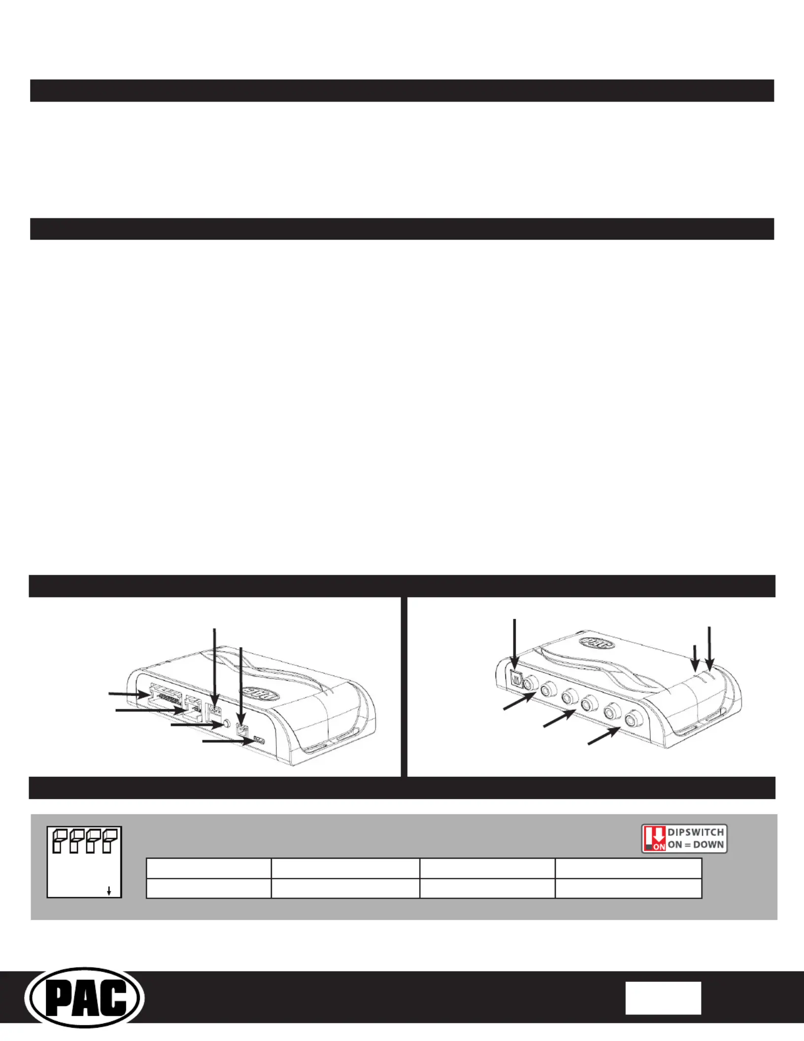
Module Layout
LED 1
Interface Connector 1
Expansion Port
TOSLINK Output
Programming Button
Feature Select
DIP switches
Front Output
Ch. 1(L) and 2(R)
Non-Fading Level Control
Knob Connection
USB Connection
Rear Output
Ch. 3(L) and 4(R)
SUB (Non-Fading)
Ch. 5 and 6
LED 2
DIP
1234
ON
Two Channel Mode5v / 4v PreoutNot UsedNot Used
1234
Set DIP switches to the ON position to activate the corresponding features.
Set DIP switches to the OFF position for any features that are not desired.
Product specificaties
| Merk: | PAC |
| Categorie: | Keverőgép |
| Model: | AP4-FD32 |
Heb je hulp nodig?
Als je hulp nodig hebt met PAC AP4-FD32 stel dan hieronder een vraag en andere gebruikers zullen je antwoorden
Handleiding Keverőgép PAC

29 Juli 2025
29 Juli 2025
11 Februari 2025
11 Februari 2025
11 Februari 2025
4 Juni 2023
Handleiding Keverőgép
Nieuwste handleidingen voor Keverőgép
20 Juli 2026
15 Juli 2026
15 Juli 2026
15 Juli 2026
15 Juli 2026
14 Juli 2026
14 Juli 2026
13 Juli 2026
13 Juli 2026
13 Juli 2026