Maico THR 10 Handleiding
Maico
Thermostaat
THR 10
Bekijk gratis de handleiding van Maico THR 10 (3 pagina’s), behorend tot de categorie Thermostaat. Deze gids werd als nuttig beoordeeld door 74 mensen en kreeg gemiddeld 3.6 sterren uit 37.5 reviews. Heb je een vraag over Maico THR 10 of wil je andere gebruikers van dit product iets vragen? Stel een vraag
Pagina 1/3

Raumthermostat
Room thermostat
w w w . m a i c o - v e n t i l a t o r e n . c o m
THR 10
Montage- und Betriebsanleitung
Mounting and Operating instructions
D
GB
1. Lieferumfang
Raumthermostat THR 10, Montage- und Betriebs-
anleitung.
2. Verwendete Symbole
2.1 Warnsymbole
GEFAHR
Lebensgefahr! Nichtbeachtung
kann zum Tod oder zu schweren
Körperverletzungen führen..
ACHTUNG Sachschäden! Nichtbeachtung
kann zu Sachschäden führen.
2.2 Sonstige Symbole
Aufzählungssymbol:
Liste mit wichtigen Informationen
zum jeweiligen Thema.
Handlungssymbol:
Liste mit durchzuführenden Tätig-
keiten. Führen Sie die angegebenen
Anweisungen der Reihe nach durch.
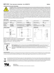
3. Produktinformationen
3.1 Produktbeschreibung
Thermostat zur Regelung von Ventilatoren, abhängig
von der Lufttemperatur. Ein interner Sensor erfasst die
Temperatur am THR 10. Bei Überschreitung des
Einschaltwertes schalten die Ventilatoren solange ein,
bis der Temperatur-Sollwert wieder unterschritten ist.
Mit Drehknopf [3] können Sie den Temperatur-Soll-
wert einstellen. Mit beiden Steckern [7] lässt sich
der Temperaturbereich auf einen Maximal- und
Minimalwert individuell eingrenzen.
THR 10 mit Schalter [3] für Sommer- oder Winter-
betrieb: Ventilator schaltet bei eingestellter
Temperatur im Sommerbetrieb ein, jedoch im
Winterbetrieb aus.
3.2 Geräteübersicht
1 Gehäuse
2 Betriebsanzeige
3 Schalter Sommer/Winter
4 Gehäuseunterteil
5 Drehknopf
6 Anschlussklemme
7 Stecker Temperaturbereich
8 Klemmenabdeckung
4. Technische Daten
Siehe auch Typenschild.
● Bemessungsspannung- 230 V
● Netzfrequenz 50 Hz / 60 Hz
● Schutzart IP 30
● Maximalbelastung (induktiv) 2 A
● Maximalbelastung (ohmsch) 10 A
● Schaltdifferenz ca. 1 K
● Sensibilität 1 K / 15 min.
● Abmessung (BxHxT) 76 x 82 x 38 mm
5. Umgebungsbedingungen und Grenzen
für den Betrieb
● Zulässige Umgebungstemperatur max. 50 °C
● Temperatur-Einstellbereich 10...30 °C
6. Grundlegende Sicherheitshinweise
6.1 Allgemeine Sicherheitshinweise
● Sicherheitshinweise vor Inbetriebnahme
aufmerksam durchlesen.
● Anleitung aufbewahren.
● Das Gerät darf nicht als Spielzeug verwendet
werden.
● Montage, elektrischer Anschluss und Repara-
turen nur durch Elektrofachkräfte zulässig.
● Gerät nur an fest verlegte elektrische Installa-
tion mit Leitungen vom Typ NYM-O oder NYM-J
(3 x 1,5 mm²) anschließen. Vorrichtung zur
Trennung vom Netz mit mind. 3 mm Kontakt-
öffnung je Pol erforderlich.
● Gerät nur mit auf Typenschild angegebener
Spannung und Frequenz betreiben.
● Keine Veränderungen am Gerät vornehmen.
● Gerät nie ohne Gehäuse [1] und Abdeckung [8]
betreiben.
Bestimmungsgemäße Verwendung
● Thermostat zur Regelung von Ventilatoren,
abhängig von der Lufttemperatur.
● Zur festen Installation in Gebäuden.
● Zur Wand-Aufputzinstallation.
● Schaltung von Drehstromventilatoren nur mit
Universalschütz.
●
Impressum: © MAICO Elektroapparate-Fabrik GmbH.
Originalanleitung. Druckfehler, Irrtümer und technische
Änderungen vorbehalten.

1. Scope of delivery
THR 10 Room thermostat, mounting and operating
instructions.
2. Symbols used
2.1 Warning symbols
DANGER
Danger to life. Non-observance can
lead to death or serious bodily injuries.
NOTICE Property damage. Non-observance
can lead to property damage.
2.2 Other symbols
List symbol: List containing impor-
tant information on the relevant subject.
Action symbol: List of work to be
carried out. Follow the instructions
in the order given.
3. Product information
3.1 Product description
Thermostat for controlling fans depending on the air
temperature. An internal sensor in the THR 10 records
temperature levels. If the switch-on point is exceeded,
the fans are switched on until the temperature drops
below the setpoint again.
The temperature setpoint value can be set using
rotary knob [3]. The temperature range can be
limited by setting maximum and minimum values
using both pins [7].
THR 10 with switch [3] for summer or winter
operation: In summer operation, the fan switches
on at the set temperature; in winter operation it
switches off.
3.2 Equipment overview
1 Housing
2 Operating display
3 Summer/Winter switch
4 Housing lower part
5 Rotary knob
6 Connecting terminal
7 Temperature range pin
8 Terminal cover
4. Technical data
See rating plate as well.
● Rated voltage 230 V
● Power frequency 50 Hz / 60 Hz
● Degree of protection IP 30
● Maximum load (inductive load) 2 A
● Maximum load (ohmic load) 10 A
● Differential gap approx. 1 K
● Sensitivity 1 K / 15 min.
● Dimensions (WxHxD) 76 x 82 x 38 mm
5. Environmental conditions and
operating limits
● Permitted ambient temperature max. 50 ℃
● Temperature setting range 10...30 °C
6. Essential safety instructions
6.1 General safety instructions
● Read the safety instructions through carefully
before commissioning.
● Keep the instructions.
● The device must not be used as a toy.
● Installation, electrical connections and repairs
only permitted when carried out by trained
specialists.
● Only connect device to permanently wired
electrical installations with NYM-O or NYM-J,
(3 x 1.5 mm²) type cables. Fixture for dis-
connectting from mains, with at least 3 mm
contact opening needed per pole.
● The fan unit may only be operated using the
voltage and frequency shown on the rating plate.
● Do not make any modifications to the fan unit.
● Never operate without the housing [1] and cover
[8] in place.
Intended use
● Thermostat for controlling fans depending on the
air temperature.
● For fixed installation in buildings.
● For surface wall mounting.
● Switching of three-phase AC fans only with
universal contactor.
6.2 Predictable misuses
Maico is not liable for damages caused by usage
not for the intended purpose.
The fan unit should not be used:
● in areas at risk from water splashes, for example
in close proximity to a shower.
● directly above a radiator.
● in the area of an air inlet (disk valve, internal
grille).
● close to flammable materials, liquids or gasses.
● in potentially explosive atmospheres
● outdoors
6.3 Safe and correct practices during operation
The unit is not intended to be used by people
whose physical, sensory or mental capabilities are
not sufficient for them to understand and put into
practice the safety information provided in these
instructions. This restriction also applies to
children. The unit may however be safely used by
such persons if they are supervised by someone
responsible for their safety or if they are instructed
in a suitable way.
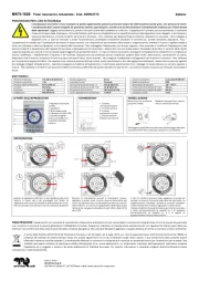
7. Installation preparations
● Recommended installation height: approx. 1.5 m
● Only install onto a dry, level surface.
●
Imprint: © Maico Elektroapparate-Fabrik GmbH.
This instruction is a translation of the German original
operating instructions. We are not responsible for
mistakes or printing errors and retain the right to make
technical modifications without giving prior notice.

NOTICE Incorrect measured values can
result from unsuitable installation
location!
Do not install the THR 10 where it
would be subject to direct exposure
to sun rays.
Do not use the THR 10 in an area
prone to draughts, hot or cold air,
e.g. near a cooker, fridge, radiator,
etc.
Do not install the THR 10 in a unit
with other heat-generating devices,
e.g. a dimmer switch.
8. Installation / Electrical connection
DANGER
Danger to life from electric shock
Switch the mains fuse off.
Position a warning notice to avoid the
unit being accidentally switched back
on.
DANGER
Danger of short-circuits caused by
pulling the power cable out.
Install an external tension relief.
NOTICE Danger of short-circuits caused by
damp if the power cable is not
inserted in the housing correctly.
Insert the power cable correctly.
Take off cover [1]. To do this, press the clip on the
lefthand side of the housing gently inwards using a
screwdriver and pull the cover off.
Fix the housing lower part [4] to the wall with two
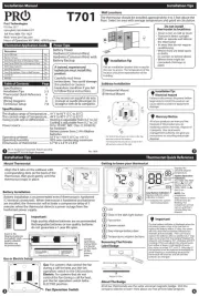
screws (see arrow in the picture in Chapter 3.2).
Suitable mounting material is to be supplied by
the customer.
Remove the terminal cover [8] and connect the
cables to the connection terminal [6] as shown in
the wiring diagram.
If the temperature range should be limited,
separate the two pins [7] from the housing
lower part.
Fit terminal cover [8].
Locate the housing [1] onto the housing lower
part [4] such that it locks into place.
Switch the mains fuse on.
8.1 Start-up
Check that the technical data has been adhered
to, by reference to the rating plate.
Carry out a function test.
9. Limiting the temperature range
DANGER
You need to use the two pins [7] to
limit the temperature range, see
"Electrical connection" Danger to
life from electric shock when the
unit is open.
Switch the mains fuse off.
Position a warning notice to avoid the
unit being accidentally switched back
on.
Remove the rotary knob [5] with a screwdriver.
Plug both pins [7] onto the back of the rotary
knob, see picture. Temperature range: Minimum
setpoint 10° C, maximum setpoint 30° C.
Reattach the rotary knob [5]. Take note of the
location of the flattened side, to ensure correct
positioning.
10. Maintenance
The unit is maintenance-free.
11. Dismantling
DANGER
Danger to life. Unit is powered
up.
Switch the mains fuse off.
Dismantling should only be carried out by a trained
electrician.
12. Disposal
Not in domestic waste.
The unit contains in part material that can be
recycled and in part substances that should not
end up as domestic waste.
Dispose of the unit once it has reached the end
of its working life according to the regulations
valid where you are.
13. Wiring diagram
To apply operating
display [2] bridge
terminals 4 and 5.
Maico Elektroapparate-Fabrik GmbH
Steinbeisstr. 20
78056 Villingen-Schwenningen
Germany
Service +49 7720 694 447
technik@maico.de
RLF.2_07.10_DSW_SM 07.10
Product specificaties
| Merk: | Maico |
| Categorie: | Thermostaat |
| Model: | THR 10 |
Heb je hulp nodig?
Als je hulp nodig hebt met Maico THR 10 stel dan hieronder een vraag en andere gebruikers zullen je antwoorden
Handleiding Thermostaat Maico

8 Juli 2023

5 Juli 2023

5 Juli 2023

1 Juli 2023

29 Juni 2023

25 Juni 2023

24 Juni 2023
Handleiding Thermostaat
- Easy Timer
- Elgato
- SPC
- REMKO
- EVE
- Truma
- Velleman
- Fantini Cosmi
- Jung
- Oregon Scientific
- Itho-Daalderop
- Finder
- Fenix
- Robertshaw
- Profile
Nieuwste handleidingen voor Thermostaat
2 September 2025
1 September 2025
30 Augustus 2025
30 Augustus 2025
26 Augustus 2025
26 Augustus 2025
26 Augustus 2025
26 Augustus 2025
26 Augustus 2025
26 Augustus 2025