Little Giant W16G07S8-32P Handleiding
Little Giant Pomp W16G07S8-32P
Bekijk gratis de handleiding van Little Giant W16G07S8-32P (24 pagina’s), behorend tot de categorie Pomp. Deze gids werd als nuttig beoordeeld door 23 mensen en kreeg gemiddeld 5.0 sterren uit 6 reviews. Heb je een vraag over Little Giant W16G07S8-32P of wil je andere gebruikers van dit product iets vragen? Stel een vraag
Pagina 1/24
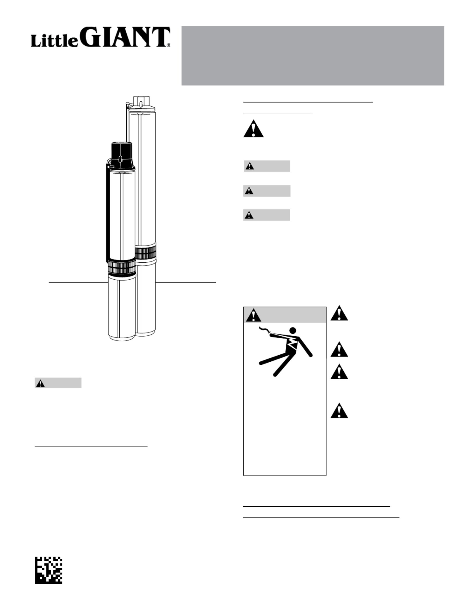
OWNER’S MANUAL
4” SUBMERSIBLE PUMP
BEFORE INSTALLING PUMP, BE SURE TO READ
THIS OWNER’S MANUAL CAREFULLY.
Fill the pump with water before starting or
the pump will be damaged. The motor on this pump is
guaranteed by the manufacturer, and in the event of failure
it must be returned to an authorized service station for
repairs. The motor warranty is void if repairs are not made
by an authorized repair station.
INSPECT THE SHIPMENT
Examine the pump when it is received to be sure there
has been no damage in shipping. Should any be evident,
report it immediately to the dealer from whom the pump
was purchased. Please check the pump package to see
that it includes pump, motor, and motor leads (if your pump
purchase includes a motor).
This pump includes either a built-in or externally-mounted
check valve with the discharge head. Make certain that your
available voltage corresponds to that of your motor.
C A U T I O N
READ AND FOLLOW SAFETY
INSTRUCTIONS
This is the safety alert symbol. When you see this
symbol on your pump or in this manual, look for one of
the following signal words and be alert to the potential for
personal injury:
D A N G E R
warns about hazards that cause serious will
personal injury, death, or major property damage if ignored.
WARNING
warns about hazards that cause serious can
personal injury, death, or major property damage if ignored.
C A U T I O N
warns about hazards that or cause willcan
minor personal injury or major property damage if ignored.
The label indicates special instructions, which are NOTICE
important but not related to hazards.
Carefully read and follow all safety instructions in this
manual and on pump.
Keep safety labels in good condition.
Replace missing or damaged safety labels.
Wire motor for correct
voltage. See Electrical
Information section of this manual
and motor nameplate.
Ground motor before
connecting to power supply.
Meet National Electrical
Code, Canadian Electrical
Code, and local codes for all
wiring.
Follow wiring instructions in
this manual when
connecting motor to power lines.
Hazardous voltage.
Can shock, burn, or
cause death.
Ground pump before
connecting to power
supply. Disconnect
power before working
on pump, motor
or tank.
WA R N I N G
Franklin Electric Co., Inc.
www.franklinwater.com
customerservice@lgpc.com
ATTENTION!
IMPORTANT INFORMATION FOR
INSTALLERS OF THIS EQUIPMENT!
THIS EQUIPMENT IS INTENDED FOR INSTALLATION BY
TECHNICALLY-QUALIFIED PERSONNEL. FAILURE TO
INSTALL IT IN COMPLIANCE WITH NATIONAL AND LOCAL
ELECTRICAL CODES AND WITH FRANKLIN ELECTRIC
RECOMMENDATIONS MAY RESULT IN ELECTRICAL SHOCK
OR FIRE HAZARD, UNSATISFACTORY PERFORMANCE,
Form 106257101 Rev. 002 11/2013
Product specificaties
| Merk: | Little Giant |
| Categorie: | Pomp |
| Model: | W16G07S8-32P |
Heb je hulp nodig?
Als je hulp nodig hebt met Little Giant W16G07S8-32P stel dan hieronder een vraag en andere gebruikers zullen je antwoorden
Handleiding Pomp Little Giant

7 Januari 2026
6 Januari 2026
28 December 2025
28 December 2025
27 December 2025
27 December 2025
25 December 2025
25 December 2025
19 December 2025
19 December 2025
Handleiding Pomp
Nieuwste handleidingen voor Pomp
5 Juni 2026
2 Juni 2026
2 Juni 2026
2 Juni 2026
1 Juni 2026
26 Mei 2026
21 Mei 2026
21 April 2026
6 April 2026
1 April 2026