Lightware HDMI-TPS-TX220 Handleiding
Lightware AV extender HDMI-TPS-TX220
Bekijk gratis de handleiding van Lightware HDMI-TPS-TX220 (2 pagina’s), behorend tot de categorie AV extender. Deze gids werd als nuttig beoordeeld door 29 mensen en kreeg gemiddeld 5.0 sterren uit 5 reviews. Heb je een vraag over Lightware HDMI-TPS-TX220 of wil je andere gebruikers van dit product iets vragen? Stel een vraag
Pagina 1/2
Quick Start Guide
DVI-HDCP-TPS-TX210, DVI-HDCP-TPS-TX220
HDMI-TPS-TX210, HDMI-TPS-TX220
DP-TPS-TX210, DP-TPS-TX220
Further information
The document is valid with the following rmware version: 1.1.4
The User’s manual of this appliance is available at www.lightware.com.
See the Downloads section on the dedicated product page.
Contact us
+36 1 255 3800
+36 1 255 3810
Lightware Visual Engineering LLC.
Peterdy 15, Budapest H-1071, Hungary
Doc. ver.: 2.1
19200111
Important Safety Instructions
Please read the supplied safety instruction document before using the product and keep it
available for future reference.
Introduction
Thank you for choosing Lightware TPS-TX200 series transmitter. The products have
HDBaseT
TM
integration with additional Lightware developments. The devices transmit HDMI/
DVI digital video signal up to 4K resolution, audio and control up to 170 m distance over a
single CAT cable (in case of DP-TPS transmitters the DP signal is converted to HDMI).
Compatible Devices
The transmitters are compatible with all Lightware
TPS receivers, matrix boards and third party
devices based on HDBase-T
TM
technology.
Power Supply Options
The transmitters can be powered:
Locally with the supplied 12V DC adaptor or Lightware’s rack mountable PSU, or
Remotely by a PoE-compatible power injector, like Lightware’s TPS-PI-1P1.
For more information please turn the paper.
TPS-TX/RX95 are not PoE-compatible, thus not able to remote power the TPS-TX200
series and vica versa. TPS-TX200 series contains PoE-compatible remote power function,
RX95 can be remote powered only by TX95 transmitter.
HDBaseT
TM
and the HDBaseT Alliance logo are trademarks of the HDBaseT Alliance.
Box ContentsConnecting Steps
* Only for DVI-HDCP-TPS-TX220, HDMI-TPS-TX220 and DP-TPS-TX220 models.
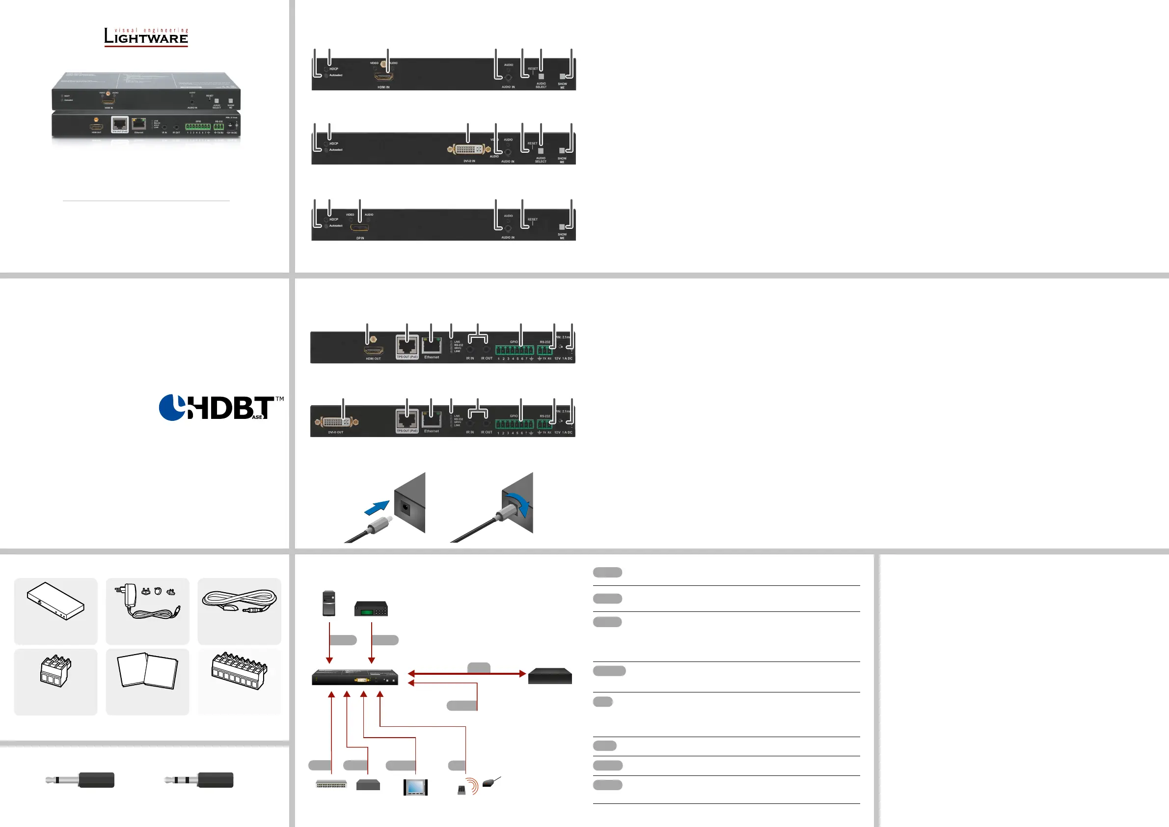
Front Views
Rear Views
Front Panel LEDs
Video Source
OFF: video source is not selected.
BLINKING: video source is selected but not active.
ON: video source is selected and active.
Audio Sources
OFF: audio source is not selected.
BLINKING: audio source is selected but not active.
ON: (with short pause): audio source is selected and the port is active but not embedded
to the output video stream (DVI output mode).
ON: (continuously): audio source is selected, the port is active and the audio is embedded
to the output video stream (HDMI output mode).
When Autoselect is enabled and audio signal is not present at all, audio LEDs blink.
HDCP LED
OFF: video output signal is not encrypted with HDCP.
ON: video output signal is encrypted with HDCP.
Autoselect LED
OFF: autoselect is disabled.
BLINKING: autoselect is enabled; searching for signal (audio LEDs also blink).
ON: autoselect is enabled; active signal is found (the LED of selected audio also lights).
Rear Panel LEDs
LIVE
OFF: device is not powered.
BLINKING (slow): device is powered and operational.
BLINKING (fast): device is in bootload mode.
ON: device is powered but no operation.
RS-232 LED
OFF: RS-232 ports (local and link) are in Pass-through mode.
BLINKING: command injection mode is active.
ON: RS-232 ports (local and link) are in Control mode.
SRVC
Reserved for future developments.
LINK
OFF: no TPS link between transmitter and receiver.
BLINKING (slow): low power mode is active.
BLINKING (fast): Ethernet fallback mode is active.
ON: TPS link is established, HDBaseT or Long Reach mode is active.
1
Autoselect LEDLED gives feedback about the current Autoselect status.
2
HDCP LEDLED gives feedback about the HDCP status of the output
signal.
3
DisplayPort inputDisplayPort connector for DisplayPort audio/video signal.
4
HDMI inputHDMI connector for DVI video or HDMI video and audio.
5
DVI-D inputDVI-I connector for DVI-D video and audio.
6
Audio input3.5 mm Jack connector for unbalanced analog audio
input signal.
7
Video select
button
Button for selecting a video source.
8
Audio select
button
Button for selecting an audio source.
9
Show me buttonSpecial functions can be reached using this button
(rmware upgrade (bootload) mode, DHCP settings,
restore factory default settings, condition launching in
Event Manager).
1
DVI-D outputLocal DVI-D output with the same A/V content as the
TPS output.
2
HDMI outputLocal HDMI output with the same A/V content as the TPS
output.
3
TPS outputLocking RJ45 connector for HDBaseT
TM
signal
transmission.
4
EthernetLocking RJ-45 connector for conguring the device using
Lightware Device Controller (LDC), or upgrading it using
Lightware Device Updater (LDU). Any third-party control
system can use this port to control the device.
5
Status LEDsThe LEDs give feedback about the actual state of the
device.
6
IR IN and IR OUT3-pole TRS connector, also known as 3.5 mm (1/8”) jack
plug for optional IR receiver (IR IN) and transmitter (IR
OUT) connection.
7
GPIO port8-pole Phoenix connector for congurable general
purpose input/output ports.
8
RS-232 port3-pole Phoenix connector for controlling the device by
LDC or third-party control systems.
9
12V DC input12V DC input for local powering.
Transmitter unit12V DC power adaptor
with interchangeable plugs
Infrared transmitter unit
Phoenix combicon
3-pole connector
Phoenix combicon
8-pole connector*
Safety and warranty info,
Quick Start Guide
Safety and
Warranty
Info
Quick
Start
Guide
Locking DC Plug
Twist 90° clockwise to lock.
DVI
Connect the source (e.g. a PC) to the DVI-I input port by a DVI cable.
Audio
Connect an audio source (e.g. a Media player) to the 3.5 analog audio input
port.
CATx
DVI
Connect the TPS output port of the transmitter to the TPS+PoE port of the
TPS-PI-1P1 by a CATx cable.
Connect the receiver (or the Matrix input board) to the power injector by a
CATx cable via the TPS port.
RS-232
Optionally for RS-232 extension: connect a controller/controlled device
(e.g. Touch panel) to the RS-232 port.
IR
Optionally for Infrared extension:
Connect the IR emitter to the IR OUT port of the transmitter, and/or
Connect the IR detector to the IR IN port of the transmitter.
LAN
Optionally connect the transmitter to a LAN.
GPIO
Optionally connect the transmitter to a LAN.
Power
Powering on the devices is recommended to do as the nal step during the
installation. Please see the Power Supply Optionssection for the details.
2 pole, 1 ring: IR transmitter3 pole, 2 rings: IR receiver
Types of IR connectors (1/8” TRS / TS)
RS-232
AudioDVI-I
GPIO
Media player
IR
Ethernet
Infrared
Relay box
LAN
Touch panel
PC
DVI-HDCP-TPS-TX220
Autoselect
HDCP
DVI-D IN
AUDIO IN
SHOW
ME
AUDIO
SELECT
RESET
VIDEO
AUDIO
AUDIO
Power
Compatible
TPS Receiver
CATx
23167
9
258167
9
248167
9
HDMI-TPS-TX220
DVI-HDCP-TPS-TX220
DP-TPS-TX220
234576
9
8
134576
9
8
HDMI-TPS-TX220, DP-TPS-TX220
DVI-HDCP-TPS-TX220
Product specificaties
| Merk: | Lightware |
| Categorie: | AV extender |
| Model: | HDMI-TPS-TX220 |
| Kleur van het product: | Zwart |
| Breedte: | 221 mm |
| Diepte: | 100.4 mm |
| Hoogte: | 26 mm |
| Soort: | AV-zender |
| LED-indicatoren: | Ja |
| Bluetooth: | Nee |
| Stroom: | 2.5 A |
| Connectiviteitstechnologie: | Bedraad |
| Ethernet LAN: | Ja |
| Maximum resolutie: | 4096 x 2048 Pixels |
| Inclusief AC-adapter: | Ja |
| Soort serieële aansluiting: | RS-232 |
| Certificering: | CE |
| HDCP: | Ja |
| Aansluiting voor netstroomadapter: | Ja |
| 3D: | Ja |
| Materiaal: | Metaal |
| HDMI versie: | 1.4 |
| Ondersteunde grafische resoluties: | 1600 x 1200 (UXGA), 1920 x 1080 (HD 1080), 3840 x 2160 |
| Remote (IR) ingang: | 1 |
| Externe adapter: | Ja |
| Rack-montage: | Ja |
| Audio-uitgangskanalen: | 7.1 kanalen |
| Compatibele producten: | HDMI-TPS-RX90\nDVI-HDCP-TPS-RX95\nHDMI-TPS-RX95\nTPS-PI-1P1\nMMX6x2-HT200\nMMX6x2-HT210\nMMX6x2-HT220 |
| Remote (IR) uitgang: | 1 |
| Power over Ethernet (PoE): | Ja |
| HDMI in: | 1 |
| RJ-45 uitgang ports: | 1 |
| Aantal HDMI-uitgangen: | 1 |
| Seriële poort(en): | 1 |
| Operating voltage: | 12 V |
| Wifi: | Nee |
| Stroomverbruik (typisch): | 8.5 W |
| Ondersteundende kabel types: | Cat5, Cat6, Cat7 |
| 3,5 mm in: | Ja |
| Extended display identification data (EDID): | Ja |
| HDCP-passthrough: | Ja |
| Geen videocompressie: | Ja |
| RS-232-passthrough: | Ja |
| EDID-geheugen (TX): | Ja |
| EDID-emulatie (TX): | Ja |
Heb je hulp nodig?
Als je hulp nodig hebt met Lightware HDMI-TPS-TX220 stel dan hieronder een vraag en andere gebruikers zullen je antwoorden
Handleiding AV extender Lightware

17 Augustus 2023
17 Augustus 2023
17 Augustus 2023
17 Augustus 2023
17 Augustus 2023
17 Augustus 2023
17 Augustus 2023
17 Augustus 2023
17 Augustus 2023
17 Augustus 2023
Handleiding AV extender
Nieuwste handleidingen voor AV extender
15 Juli 2026
14 Juli 2026
9 Juli 2026
24 Juni 2026
23 Juni 2026
10 Juni 2026
10 Juni 2026
8 Juni 2026
8 Juni 2026
23 Mei 2026