Lightware DVI-HDCP-TPS-TX95 Handleiding
Lightware AV extender DVI-HDCP-TPS-TX95
Bekijk gratis de handleiding van Lightware DVI-HDCP-TPS-TX95 (2 pagina’s), behorend tot de categorie AV extender. Deze gids werd als nuttig beoordeeld door 27 mensen en kreeg gemiddeld 4.7 sterren uit 8 reviews. Heb je een vraag over Lightware DVI-HDCP-TPS-TX95 of wil je andere gebruikers van dit product iets vragen? Stel een vraag
Pagina 1/2
Quick Start Guide
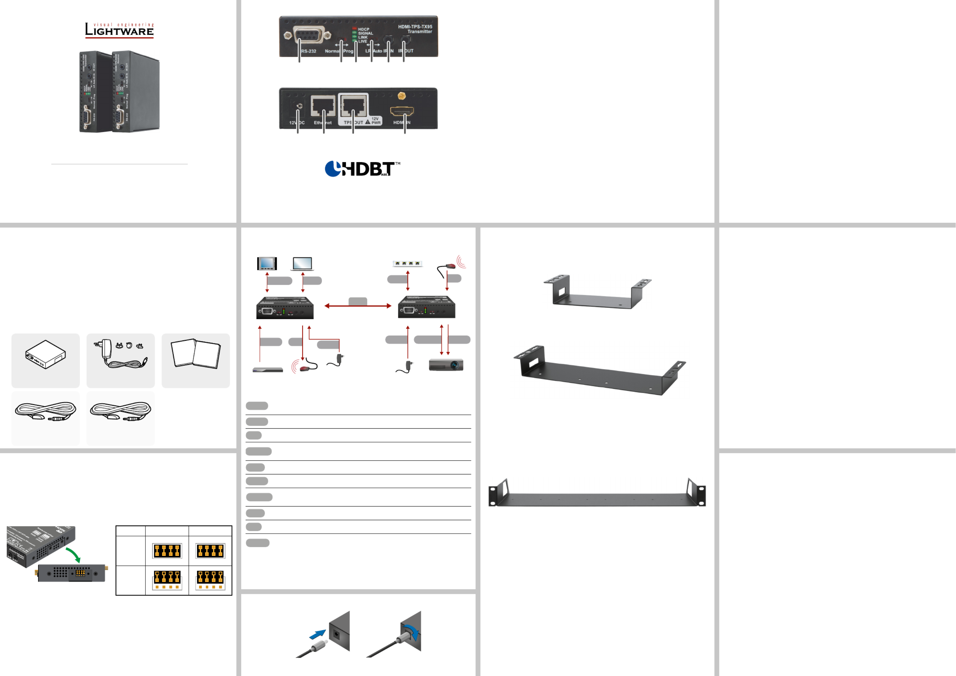
HDMI-TPS-TX95
HDMI-TPS-RX95
DVI-HDCP-TPS-TX95
DVI-HDCP-TPS-RX95
Further Information
The Product brief of this appliance and further information is available at www.lightware.com.
See the section on the dedicated product page.Downloads
Contact Us
sales@lightware.com
+36 1 255 3800
support@lightware.com
+36 1 255 3810
Lightware Visual Engineering LLC.
Peterdy 15, Budapest H-1071, Hungary
Doc. ver.: 2.1
19200118
Locking DC Plug
Twist 90° clockwise to lock.
Connecting Steps
1
RS-232 portLocal RS-232 port for bidirectional serial data connection and
performing rmware upgrade (programming).
2
RS-232 switchNormal: serial data is passed through the device.
Prog: RS-232 pass-through function is disabled, the device is
ready for the rmware upgrade.
3
Status LEDsSee the next section.
4
TPS mode
switch
LR: Long reach TPS mode; lower resolution (max 1080p),
longer distances; : TPS mode is determined automatically.Auto
5
IR inputIR signal input connector (for 3.5 mm Jack, 3-pole, TRS plug).
6
IR outputIR signal output connector (for 3.5 mm Jack, 2-pole, TS plug).
7
DC input12V DC input for local power supply.
8
Ethernet portThe Ethernet data is passed through the device.
9
TPS portTPS port to the other compatible device (extender / matrix /
board).
q
HDMI portVideo port for DVI or HDMI signal.
Front and Rear View – Legend
Important Safety Instructions
Please read the supplied safety instruction document before using the product and keep it
available for future reference.
Introduction
The HDMI-TPS-RX/TX95 and DVI-HDCP-TPS-RX/TX95 are DVI 1.0 and HDMI 1.4
compatible long-distance extenders. The difference between HDMI and DVI-HDCP models
is just the HDMI and DVI connector. The units offer bi-directional RS-232, Infra-Red (IR), and
Ethernet signal pass-through on the same CAT5e...CAT7 cable that carries the uncompressed
HDMI video and audio signal.
Box Contents
Remote Power Options
The TPS extenders can be powered remotely by its extender pair or a TPS matrix board. This
feature can be enabled or disabled with jumper settings. Switch off the extenders. Loose the
screws and remove the small plate from the right side of the enclosure. To enable the remote
power function place the jumper block onto all the pinheads. To disable it place the jumper
block onto the upper line pinheads only. In case of enabled remote power on both extenders
the local adaptor can be placed at any side.
The TPS remote powering must be used only with 95 series TPS extenders and MX
TPS matrix boards. Using it with other devices may damage both units. Connecting
incompatible devices with similar connectors may cause harm to the devices. Never
connect any third party device to the extender with remote powering!
AWG 26 cables are not recommended with remote powering (reduce cable distances).
Extender unit12V DC adaptor with
interchangeable plugs
Infrared detector unit
(for RX95)
Infrared emitter unit
(for TX95)
Safety and Warranty info,
Quick Start Guide
Front View
Rear View
The transmitters and the receivers have the same construction and connectors.
The product is compatible with
HDBaseT
TM
and the HDBaseT Alliance logo are trademarks of the HDBaseT Alliance.
Status LEDs
HDCP
OFF: video output signal is not encrypted with HDCP.
ON: video output signal is encrypted with HDCP.
VIDEO
OFF: no video signal transmission.
ON: video signal transmission.
LINK
OFF: TPS connection failed between the devices.
BLINKING: TPS connection is detected and LPPF link mode is active.
ON: TPS connection is detected and HDBT or LR link mode is active.
LIVE
OFF: no power supply or out of order.
BLINKING: device is powered and ready to use.
TPS link modes
If an extender and a TPS matrix board are paired the board forces the extender to use the
settings of the matrix. The extender’s TPS mode switch has no effect. For detailed information
about the TPS link modes in case of matrix boards see the user’s manual of the matrix.
Installation of the Extender with a Matrix
1. Power off all devices. (Installing with powered devices may harm them.)
2. Check the RS-232 switch(es) on the extender(s); they must be in Normal position.
3. The state of the TPS link mode switch makes no difference on the extender because the
connected board forces the extender to use the settings of the matrix.
4. Set the remote power mode of the matrix boards with the jumpers on them. Every port
can be set for remote powering separately. To enable the remote power function place
the jumper block onto all the pinheads of the desired port. To disable it remove the jumper
block. For detailed information, see the user’s manual of the matrix.
5. Set the extenders’ remote power mode with the same method as it mentioned in the
standalone case.
6. Pair the extender(s) and the matrix board(s) with CATx cable(s). The transmitters’ TPS
OUT with the input boards’ TPS IN and the receivers’ TPS IN with the output boards’
TPS OUT.
7. Connect the video source(s), sink(s) and the desired accessory device(s) to the matrix
(MX-TPS boards don’t support the IR pass-through).
8. Connect the video source(s), sink(s) and the desired accessory device(s) to the extend-
ers.
9. Supply that matrix boards with 12V 6,67A DC which have ports with enabled remote
powering.
10. Supply the extenders with 12V 2A DC. If the remote power is disabled on the connected
matrix card’s port, local adaptor must be used for the extender.
11. Connect the power cord of the matrix into the outlet and switch on the matrix.
12. Supply the other connected units.
Safety and
Warranty
Info
Quick
Start
Guide
124 536
987 q
Mounting Options
Lightware offers three types of mounting accessory to x the extenders:
Under Desk Mounting Kit (UD-kit)
The UD-kit makes easy to mount one extender under any at surface (e.g. furniture).
UD Mounting Kit Double (UD-kit double)
The UD-kit double makes easy to mount two extenders under any at surface (e.g. furniture).
Rack Shelf
1U high rack shelf provides mounting holes for fastening up to extenders.four
Mounting Steps
Always use the xing screws which are supplied with the mounting accessory. If
you insert screws longer than 6 mm, the device can be damaged.
1. Unplug all the cables connected to the device(s).
2. Turn the device(s) upside down.
3. Put the shelf upside down on the device(s). Position it to get the mounting holes aligned.
4. Fasten the device on the shelf with the provided screws.
5. Fix the shelf to the desired place (screws are not supplied).
CATx
Connect the TPS output port of the Transmitter to the TPS input port of the
Receiverby a CATx cable.
HDMI
Connect a source to the HDMI (DVI-D) input port of the transmitter.
IR
Connect an IR emitter unit to the IR output port of the transmitter.
RS-232
Connect a controller device to the local RS-232 port of the transmitter.
Make sure the RS-232 switch is in position.Normal
LAN
Optionally connect a laptop to the Ethernet port of the transmitter.
HDMI
Connect a sink device to the HDMI (DVI-D) output port of the receiver.
RS-232
Connect a serial cable between the sink device and the RS-232 port of the
receiver.
LAN
Connect the receiver to Ethernet by a CATx cable.
IR
Connect an IR detector unit to the IR input port of the receiver.
Power
Firstly connect the power adaptor to the DC input of the power injector, then
secondly to the AC power socket.
TX sideRX side
Enabled
Disabled
(default)
RS-232
HDMI Power
Power HDMI
IR
Touch panel
Blu-ray playerIR emitter
Ethernet switchIR detector
Power adaptor
Power
adaptor
Laptop
Projector
HDMI-
TPS-TX95
HDMI-
TPS-RX95
CATx
RS-232 LANIR
LAN
RS-232Normal ProgIR INIR OUT
HDMI-TPS-TX95
Transmitter
LR Auto
SIGNAL
LIVE
LINK
HDCP
RS-232NormalProgIR INIR OUT
HDMI-TPS-RX95
Receiver
LR Auto
SIGNAL
LIVE
LINK
HDCP
Product specificaties
| Merk: | Lightware |
| Categorie: | AV extender |
| Model: | DVI-HDCP-TPS-TX95 |
| Kleur van het product: | Zwart |
| Soort: | AV-zender |
| LED-indicatoren: | Ja |
| Bluetooth: | Nee |
| Stroom: | 2.5 A |
| Connectiviteitstechnologie: | Bedraad |
| Ethernet LAN: | Ja |
| Ondersteunde video-modi: | 1080p |
| Maximum resolutie: | 1920 x 1200 Pixels |
| Inclusief AC-adapter: | Ja |
| Soort serieële aansluiting: | RS-232 |
| Certificering: | CE |
| HDCP: | Ja |
| Aansluiting voor netstroomadapter: | Ja |
| 3D: | Ja |
| Materiaal: | Metaal |
| Ondersteunde grafische resoluties: | 1920 x 1200 (WUXGA) |
| Remote (IR) ingang: | 1 |
| Externe adapter: | Ja |
| Remote (IR) uitgang: | 1 |
| DVI input ports: | 1 |
| RJ-45 uitgang ports: | 2 |
| IR-doorvoer: | Ja |
| Bandbreedte: | 3.4 Gbit/s |
| Seriële poort(en): | 1 |
| Operating voltage: | 12 V |
| Maximaal bereik: | 170 m |
| Wifi: | Nee |
| Transmitter afmetingen (WxDxH): | 100.4 x 100.4 x 26 mm |
| Transmitter gewicht: | 330 g |
| Stroomverbruik (zender) (max): | 4.2 W |
| Ondersteundende kabel types: | Cat5, Cat6, Cat7 |
| Extended display identification data (EDID): | Ja |
| HDCP-passthrough: | Ja |
| Geen videocompressie: | Ja |
| Stroomverbruik (TX): | 3.6 W |
| RS-232-passthrough: | Ja |
Heb je hulp nodig?
Als je hulp nodig hebt met Lightware DVI-HDCP-TPS-TX95 stel dan hieronder een vraag en andere gebruikers zullen je antwoorden
Handleiding AV extender Lightware

17 Augustus 2023
17 Augustus 2023
17 Augustus 2023
17 Augustus 2023
17 Augustus 2023
17 Augustus 2023
17 Augustus 2023
17 Augustus 2023
17 Augustus 2023
17 Augustus 2023
Handleiding AV extender
Nieuwste handleidingen voor AV extender
15 Juli 2026
14 Juli 2026
9 Juli 2026
24 Juni 2026
23 Juni 2026
10 Juni 2026
10 Juni 2026
8 Juni 2026
8 Juni 2026
23 Mei 2026