Konig CMP-NWIPCAM31 Handleiding
Bekijk gratis de handleiding van Konig CMP-NWIPCAM31 (129 pagina’s), behorend tot de categorie Webcam. Deze gids werd als nuttig beoordeeld door 15 mensen en kreeg gemiddeld 4.8 sterren uit 7 reviews. Heb je een vraag over Konig CMP-NWIPCAM31 of wil je andere gebruikers van dit product iets vragen? Stel een vraag
Pagina 1/129
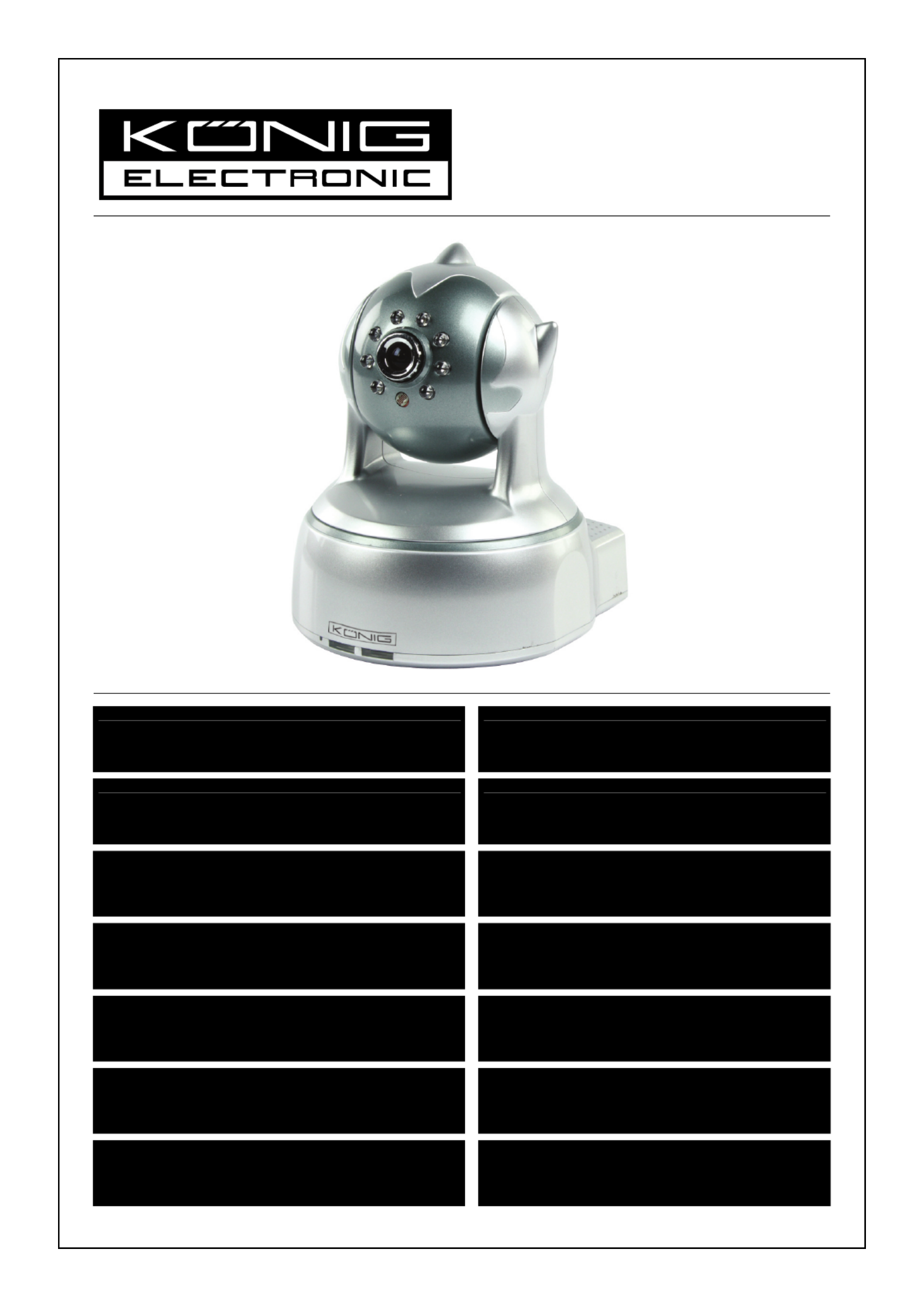
CMP-NWIPCAM22
CMP-NWIPCAM31
MANUAL (p. 2)
IP Wireless Network Camera
ANLEITUNG (S. 11)
IP WLAN-Netzwerkkamera
MODE D’EMPLOI (p. 20)
Caméra à adresse IP de réseau sans fil
GEBRUIKSAANWIJZING (p. 29)
Draadloze IP-netwerkcamera
MANUALE (p. 38)
Videocamere di rete IP wi-fi
MANUAL DE USO (p. 47)
Cámara de Red IP Inalámbrica
HASZNÁLATI ÚTMUTATÓ (o. 56.)
Vezeték nélküli hálózati IP kamera
KÄYTTÖOHJE (s. 65)
Langaton IP-verkkokamera
BRUKSANVISNING (s. 74)
IP Trådlös nätverkskamera
NÁVOD K POUŽITÍ (s. 83)
IP bezdrátová síťová kamera
MANUAL DE UTILIZARE (p. 92)
Cameră video IP cu conectare wireless
ΕΓΧΕΙΡΙΔΙΟ XPHΣ ΣH (σελ. 101)
Ασύρματηκάμεραδικτύου IP
BRUGERVEJLEDNING (s. 110)
IP Trådløst netværkskamera
VEILEDNING (s. 119)
IP trådløstnettverkskamera
Product specificaties
| Merk: | Konig |
| Categorie: | Webcam |
| Model: | CMP-NWIPCAM31 |
| Kleur van het product: | Zilver |
| Montagewijze: | Standaard |
| Maximale beeldsnelheid: | 30 fps |
| Megapixels: | 0.3 MP |
| Maximale beeldresolutie: | - Pixels |
| Ingebouwde flitser: | Ja |
| Maximale videoresolutie: | 640 x 480 Pixels |
| Ingebouwde microfoon: | Ja |
| Nachtmodus: | Ja |
| Bekabelingstechnologie: | 10-Base-T/100-Base-TX |
| Compatibele besturingssystemen: | Windows 2000, XP, Vista, 7 |
| Ondersteunde netwerkprotocollen: | TCP/IP, UNDP/IP, HTTP, SMTP, FTP, DHCP, DDNS, UPNP, NTP, PPPOE |
| Pan bereik: | 0 - 350 ° |
| Wifi: | Ja |
| Bereik kantelhoek: | 0 - 100 ° |
Heb je hulp nodig?
Als je hulp nodig hebt met Konig CMP-NWIPCAM31 stel dan hieronder een vraag en andere gebruikers zullen je antwoorden
Handleiding Webcam Konig

20 Mei 2023
11 April 2023
5 Maart 2023
13 Februari 2023
7 Februari 2023
31 Januari 2023
Handleiding Webcam
Nieuwste handleidingen voor Webcam
15 Juli 2026
12 Mei 2026
8 Mei 2026
6 Mei 2026
25 April 2026
15 April 2026
6 April 2026
12 Maart 2026
11 Maart 2026
5 Maart 2026