Klein Tools VDV512-100 Handleiding
Klein Tools Meetapparatuur VDV512-100
Bekijk gratis de handleiding van Klein Tools VDV512-100 (368 pagina’s), behorend tot de categorie Meetapparatuur. Deze gids werd als nuttig beoordeeld door 83 mensen en kreeg gemiddeld 4.9 sterren uit 8 reviews. Heb je een vraag over Klein Tools VDV512-100 of wil je andere gebruikers van dit product iets vragen? Stel een vraag
Pagina 1/368
GENERAL SPECIFICATIONS
The Klein Tools Coax Explorer
®
2 verifies proper continuity of F-connector coaxial cables and
maps their location. The color-coded push-on remotes allow for up to four cables to be tested
and mapped, displaying cable status via LED indicators (PASS, OPEN, or SHORT) that also
identify the cable/remote location.
• Environment: Indoor
• Operating Altitude: 10000 ft. (3000 m) maximum
• Operating Temperature: 32° to 122°F (0° to 50°C)
• Storage Temp: -4° to 140°F (-20° to 60°C)
• Relative Humidity: 10% to 90% non-condensing
• Dimensions (including remote holder): 5.7" x 2.3" x 1.1" (145 x 32 x 29 mm)
• Weight (including batteries): 4.8 oz. (136 g)
Specifications subject to change.
TESTING/MAPPING CABLES
NOTE: Not for use on powered circuits or outlets.
1.Connect a test remote
1
,
2
,
3
or
4
to one end of the cable or outlet to be
tested. If necessary, use the included F-adapter
9
to connect the test remote to the
cable. If mapping, install remaining remotes to additional locations.
2.
Connect the opposite end of the cable or outlet to be tested to the F-connector
5
on
the Coax Explorer
®
2.
3.
Press and hold the TEST button
10
. If the cable is wired correctly, one of the four PASS
LEDs
11
will light, also indicating the cable/remote location. If there is a problem with
the cable, one of the FAULT LEDs (OPEN
12
or SHORT
13
) will light.
4.
Repeat steps 2 and 3 to test/map additional cables.
TESTING AN UNINSTALLED CABLE
1.Using the included F-adapter
9
, connect a test remote
1
to one end of the cable to be
tested.
2.
Connect the opposite end of the cable to be tested to the F-connector
5
on the Coax
Explorer
®
2.
3.
Press and hold the TEST button
10
. If the cable is wired correctly, the corresponding
PASS LED
11
will light. If there is a problem with the cable, one of the FAULT LEDs
(OPEN
12
or SHORT
13
) will light.
REMOTE HOLDER/STORAGE
The test remotes conveniently snap into the remote holder
8
for storage. To store the
included F-adapter
9
, push two remotes onto the adapter before snapping the remotes into
the holder.
The remote holder snaps onto the body of the Coax Explorer
®
2 and may be removed if
desired. Hold the tester in one hand and apply slight downward pressure to one side of the
remote holder with the other hand to release it from the tester. To reattach, align the holder
with the tester body and snap back into place.
BATTERY REPLACEMENT (FIG. 1)
When the TEST button is pressed and no LEDs light, the batteries must be replaced.
1.Unscrew the battery cap
6
.
2.Remove and recycle the two spent AAA batteries
7
.
3.
Install two new AAA batteries, with the positive (+) side facing into the tester as shown.
4.Screw battery cap tightly back into place.
STORAGE
Remove the batteries when the tester is not in use for a prolonged period of time. Do not expose
to high temperatures or humidity. After a period of storage in extreme conditions exceeding the
limits mentioned in the GENERAL SPECIFICATIONS section, allow the tester to return to normal
operating conditions before using.
FCC AND IC COMPLIANCE
See this product’s page at www.kleintools.com for FCC compliance information.
Canada ICES-003 (B) / NMB-003 (B)
WARRANTY
www.kleintools.com/warranty
DISPOSAL / RECYCLE
Do not place equipment and its accessories in the trash. Items must be properly
disposed of in accordance with local regulations. Please see
www.epa.gov/recycle for additional information.
CUSTOMER SERVICE
KLEIN TOOLS, INC.
450 Bond Street, Lincolnshire, IL 60069 1-800-553-4676
[email protected] www.kleintools.com
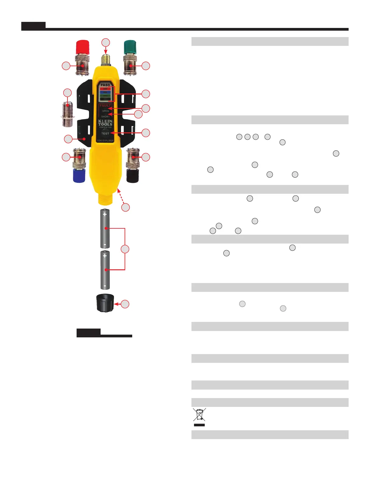
FIG. 1
5
8
13
10
12
13
11
4
9
2
14
7
6
ENGLISH
ENGLISH
1.
Test Remote #1 (Red)
2.
Test Remote #2 (Blue)
3.
Test Remote #3 (Green)
4.
Test Remote #4 (Black)
5.
F-Connector
6.
Battery Cap
7.
2x AAA Batteries
(included)
8.
Remote Holder
9.
F-Adapter
10.
TEST Button
11.
PASS LEDs
12.
OPEN Fault LED
13.
SHORT Fault LED
14.
Pocket Clip (Back)
NOTE: There are no
user-serviceable
parts inside tester.
VDV512-101 Instructions
BASED ON 1330430 Rev. 11/21 E
Product specificaties
| Merk: | Klein Tools |
| Categorie: | Meetapparatuur |
| Model: | VDV512-100 |
| Gewicht: | 85 g |
| Breedte: | 32 mm |
| Diepte: | 146 mm |
| Hoogte: | 25 mm |
| Ondersteund aantal accu's/batterijen: | 2 |
| Type batterij: | AAA |
| Ondersteunde aansluitingen: | BNC, RJ-11 |
Heb je hulp nodig?
Als je hulp nodig hebt met Klein Tools VDV512-100 stel dan hieronder een vraag en andere gebruikers zullen je antwoorden
Handleiding Meetapparatuur Klein Tools

4 Mei 2026
6 Maart 2026
2 Maart 2026
8 Juli 2025
14 April 2025
13 Januari 2025
13 Januari 2025
18 November 2024
12 November 2024
24 September 2024
Handleiding Meetapparatuur
Nieuwste handleidingen voor Meetapparatuur
21 Mei 2026
19 Mei 2026
18 Mei 2026
15 Mei 2026
14 Mei 2026
14 Mei 2026
12 Mei 2026
12 Mei 2026
12 Mei 2026
12 Mei 2026