Klein Tools HVCT1 Handleiding
Klein Tools Meetapparatuur HVCT1
Bekijk gratis de handleiding van Klein Tools HVCT1 (14 pagina’s), behorend tot de categorie Meetapparatuur. Deze gids werd als nuttig beoordeeld door 87 mensen en kreeg gemiddeld 4.9 sterren uit 2 reviews. Heb je een vraag over Klein Tools HVCT1 of wil je andere gebruikers van dit product iets vragen? Stel een vraag
Pagina 1/14
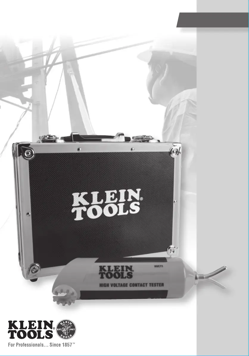
INSTRUCTION MANUAL
High-Voltage Contact Tester
5kV to 36kV AC
HVCT1
KLEIN TOOLS, INC. 450 Bond Street Lincolnshire, IL 60069 USA
Product specificaties
| Merk: | Klein Tools |
| Categorie: | Meetapparatuur |
| Model: | HVCT1 |
Heb je hulp nodig?
Als je hulp nodig hebt met Klein Tools HVCT1 stel dan hieronder een vraag en andere gebruikers zullen je antwoorden
Handleiding Meetapparatuur Klein Tools

4 Mei 2026
6 Maart 2026
2 Maart 2026
8 Juli 2025
14 April 2025
13 Januari 2025
13 Januari 2025
18 November 2024
12 November 2024
24 September 2024
Handleiding Meetapparatuur
Nieuwste handleidingen voor Meetapparatuur
21 Mei 2026
19 Mei 2026
18 Mei 2026
15 Mei 2026
14 Mei 2026
14 Mei 2026
12 Mei 2026
12 Mei 2026
12 Mei 2026
12 Mei 2026