Johnson Control T600MSP-3 Handleiding
Johnson Control
Thermostaat
T600MSP-3
Bekijk gratis de handleiding van Johnson Control T600MSP-3 (16 pagina’s), behorend tot de categorie Thermostaat. Deze gids werd als nuttig beoordeeld door 69 mensen en kreeg gemiddeld 4.4 sterren uit 35 reviews. Heb je een vraag over Johnson Control T600MSP-3 of wil je andere gebruikers van dit product iets vragen? Stel een vraag
Pagina 1/16

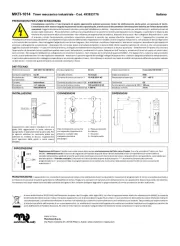
T600MSx-3 Multi-Stage Thermostat Installation Instructions 1
Applications
The T600MSN-3 non-programmable and T600MSP-3
programmable thermostats are specifically designed
for control of multi-stage commercial heating and
cooling equipment.
North American Emissions Compliance
United States
This equipment has been tested and found to comply
with the limits for a Class A digital device pursuant to
Part 15 of the FCC Rules. These limits are designed to
provide reasonable protection against harmful
interference when this equipment is operated in a
commercial environment. This equipment generates,
uses, and can radiate radio frequency energy and, if
not installed and used in accordance with the
instruction manual, may cause harmful interference to
radio communications. Operation of this equipment in a
residential area is likely to cause harmful interference,
in which case the user will be required to correct the
interference at his/her own expense.
Canada
This Class (A) digital apparatus meets all the
requirements of the Canadian Interference-Causing
Equipment Regulations.
Cet appareil numérique de la Classe (A) respecte
toutes les exigences du Règlement sur le matériel
brouilleur du Canada.
Installation
Location Considerations
Locate the T600MSx-3 thermostat:
• on a partitioning wall, approximately 5 ft (1.5 m)
above the floor in a location of average
temperature
• away from direct sunlight, radiant heat, outside
walls, behind doors, air discharge grills, stairwells,
or outside doors
• away from steam or water pipes, warm air stacks,
unconditioned areas (not heated or cooled), or
sources of electrical interference
Note: Allow for vertical air circulation to the
T600MSx-3 thermostat.
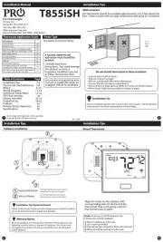
To install the thermostat:
1. Use a Phillips-head screwdriver to remove the
security screw on the bottom of the thermostat
cover.
2. Pull the bottom edge of the thermostat cover and
open the thermostat as illustrated in Figure 1.
IMPORTANT: The T600MSx-3 Thermostat is
intended to provide an input to equipment under
normal operating conditions. Where failure or
malfunction of the thermostat could lead to personal
injury or property damage to the controlled
equipment or other property, additional precautions
must be designed into the control system.
Incorporate and maintain other devices such as
supervisory or alarm systems or safety or limit
controls intended to warn of or protect against failure
or malfunction of the thermostat.
Figure 1: Removing the Thermostat Cover
FIG:cvr_rmvl
T600MSx-3 Multi-Stage Thermostat
Installation Instructions
T600MSN-3, T600MSP-3 Part No. 24-9890-617, Rev. —
Issued September 18, 2006

T600MSx-3 Multi-Stage Thermostat Installation Instructions2
3. Carefully pull the locking tabs on the right side of
the thermostat mounting base and unlock the
Printed Circuit Board (PCB). Open the PCB to the
left as illustrated in Figure 2.
4. Pull approximately 6 in. (152 mm) of wire from the
wall and insert the wire through the hole in the
thermostat mounting base.
5. Align the thermostat mounting base on the wall and
use the base as a template to mark the two
mounting hole locations.
Note: Be sure to position the thermostat mounting
base so that the arrow on the base points upward to
indicate the top of the thermostat.
6. Drill a 3/16 in. (5 mm) hole at each of the two
marked locations and tap nylon anchors (included
with the thermostat) flush to the wall surface.
7. Position the thermostat mounting base on the wall
and use the two mounting screws (included with
the thermostat) to secure the base to the surface
as illustrated in Figure 3.
Note: Be careful not to overtighten the mounting
screws.
8. Swing the PCB back to the right and carefully snap
it into the locking tabs on the thermostat mounting
base.
9. Pull the pull-tabs on each of the connectors and
remove the screw terminal blocks as illustrated in
Figure 4.
Wiring
When an existing thermostat is replaced, remove and
label the wires to identify the terminal functions. When
a T600MSx-3 thermostat is replaced, simply remove
the old screw terminal blocks and reinsert them onto
the PCB of the replacement thermostat.
Figure 2: Opening the Thermostat PCB
FIG:prntd_crct_brd
PCB
Locking
Tabs
Figure 3: Securing the Thermostat
Mounting Base to the Wall
FIG:mntng_bs
!
CAUTION: Risk of Electric Shock.
Disconnect the power supply before
making electrical connections to avoid
electric shock.
!
CAUTION: Risk of Property Damage.
Do not apply power to the system before
checking all wiring connections. Short
circuited or improperly connected wires
may result in permanent damage to the
equipment.
IMPORTANT: Make all wiring connections in
accordance with local, national, and regional
regulations. Do not exceed the electrical ratings of
the T600MSx-3 thermostat.
Figure 4: Removing the Screw Terminal Blocks
FIG:trmnl_blcks

T600MSx-3 Multi-Stage Thermostat Installation Instructions 3
To wire the thermostat:
1. Strip the ends of each wire a 1/4 in. (6 mm) and
connect them to the appropriate screw terminals as
indicated in Figure 5.
2. Carefully push any excess wire back into the wall.
Seal the hole in the wall with fireproof material to
prevent drafts from affecting the ambient
temperature readings.
3. Reinsert the screw terminal blocks onto the PCB.
4. Reattach the thermostat cover to the mounting
base (top side first).
Note: Use a Phillips-head screwdriver to reinstall the
security screw on the bottom of the thermostat cover.
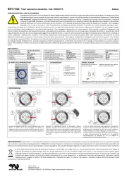
Figure 5: Terminal Blocks
Y2 Y1 G RC CRHW1W2
D1 D2 RS
Scom
5 pole left top connector 3 pole right top
connector
7 pole bottom connector
OS MS
AUX
12345678
10 11 12 14 15 16
13
FIG:T600MSx_trmblk
Table 1: Terminal Identification (See Figure 5.)
Number Label Function
1Y2Energizes on a call for second-stage
cooling.
2Y1Energizes on a call for first-stage
cooling.
3GEnergizes fan in accordance with
selected fan mode.
4RC24 VAC from equipment transformer
5C24 VAC (Common) from equipment
transformer
6RH24 VAC for heating stage
7W1Energizes on a call for first-stage
heating.
8W2Energizes on a call for second-stage
heating.
10 Aux Auxiliary output
11 DI1 Configurable Digital Input 1
12 DI2 Configurable Digital Input 2
13 RS Remote Room Temperature Sensor
14 Scom Sensor Common
15 OS Outdoor Air Sensor
16 MS Not Used
Figure 6: Wiring the T600MSx-3 Thermostats
Cool 2
24 VAC
Thermostat Power
Y2 Y1 GRCC
If using the same power source
for the thermostat and heating
loads, install a jumper
across RC and RH.
Heat 1 Heat 2
RH W1 W2
Fan
Cool 1
D2
Scom
RS
D1
Remote
Room
Sensor
OS
Remote
Outdoor
Sensor
Aux
AUX
Cool 2
FIG:T600MSx_wir
Isolated Contact
- Lighting
- On/Off Actuation
- Exhaust Fan
Product specificaties
| Merk: | Johnson Control |
| Categorie: | Thermostaat |
| Model: | T600MSP-3 |
Heb je hulp nodig?
Als je hulp nodig hebt met Johnson Control T600MSP-3 stel dan hieronder een vraag en andere gebruikers zullen je antwoorden
Handleiding Thermostaat Johnson Control

30 Juli 2023

30 Juli 2023

30 Juli 2023

30 Juli 2023

30 Juli 2023
Handleiding Thermostaat
- IMIT
- EBERLE
- Seitron
- Computherm
- Jablotron
- Otio
- ELKO
- Dimplex
- ACV
- Brink
- Arnold Rak
- Ferroli
- Tylö
- Buderus
- TP Link
Nieuwste handleidingen voor Thermostaat
2 September 2025
1 September 2025

30 Augustus 2025
30 Augustus 2025
26 Augustus 2025
26 Augustus 2025
26 Augustus 2025
26 Augustus 2025

26 Augustus 2025
26 Augustus 2025