Janitza UMG 103-CBM Handleiding
Janitza Niet gecategoriseerd UMG 103-CBM
Bekijk gratis de handleiding van Janitza UMG 103-CBM (62 pagina’s), behorend tot de categorie Niet gecategoriseerd. Deze gids werd als nuttig beoordeeld door 101 mensen en kreeg gemiddeld 4.2 sterren uit 2 reviews. Heb je een vraag over Janitza UMG 103-CBM of wil je andere gebruikers van dit product iets vragen? Stel een vraag
Pagina 1/62
Doc. no. 2.057.013.1.e 05/2023
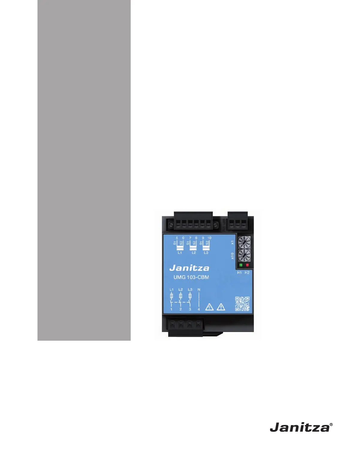
Power Quality Analyser
UMG 103-CBM
(from firmware 2.0)
User manual and technical data
Janitza electronics GmbH
Vor dem Polstück 6
35633 Lahnau | Germany
Support +49 6441 9642-22
[email protected] | www.janitza.com
www.janitza.com
Product specificaties
| Merk: | Janitza |
| Categorie: | Niet gecategoriseerd |
| Model: | UMG 103-CBM |
Heb je hulp nodig?
Als je hulp nodig hebt met Janitza UMG 103-CBM stel dan hieronder een vraag en andere gebruikers zullen je antwoorden
Handleiding Niet gecategoriseerd Janitza

2 Juni 2026
11 Februari 2026
3 Februari 2026
3 Februari 2026
2 Februari 2026
30 Januari 2026
27 Januari 2026
21 Januari 2026
13 Mei 2025
13 Mei 2025
Handleiding Niet gecategoriseerd
Nieuwste handleidingen voor Niet gecategoriseerd
23 Juli 2026
23 Juli 2026
23 Juli 2026
22 Juli 2026
22 Juli 2026
22 Juli 2026
22 Juli 2026
22 Juli 2026
22 Juli 2026
21 Juli 2026