Janitza EMD 485-P1 Handleiding
Janitza Niet gecategoriseerd EMD 485-P1
Bekijk gratis de handleiding van Janitza EMD 485-P1 (2 pagina’s), behorend tot de categorie Niet gecategoriseerd. Deze gids werd als nuttig beoordeeld door 12 mensen en kreeg gemiddeld 4.4 sterren uit 6 reviews. Heb je een vraag over Janitza EMD 485-P1 of wil je andere gebruikers van dit product iets vragen? Stel een vraag
Pagina 1/2
Introduction
This document provides instructions for
installation, operation, and maintenance.
Device description
The energy meter (device) with back-lighted LCD
screen is designed for single-phase applications
in industrial, utility and residential areas. It
measures important electrical parameters like
voltage, frequency, current, power, active and
reactive energy. The energy measurement is
bidirectional, i.e. imported and exported energy
are measured separately, so that, for example,
the solar gain of a PV system can also be
recorded.
The maximum demand (current and power)
can be measured over preset periods of up to
60minutes.
The device provides an RS485 serial port with
Modbus RTU protocol for communication and
to enable remote monitoring and control of the
device.
Intended use
The MID-certified device is intended for the
following uses:
• Measurement of power and cumulative energy
in accordance with classC EN50470-3/
ANSIC12-20:2010 in single-phase networks
(1p2w).
• Installation in wheather-protected switchboard
cabinets and small distribution boards in
industrial and residential environments. The
installation position is arbitrary.
• For indoor use only.
• Use in accordance with national specifications.
Improper use:
The following is considered improper use in the
sense of foreseeable misuse:
• Operation outside the specifications, e.g.,
regarding operating/measuring voltage or
current, environmental specifications, etc.
• Too high or wrong external back-up fuse (see
fig.3).
• Installation in vehicles! Use of the device
in non-stationary equipment constitutes an
exceptional environmental condition and is
only permissible by special agreement.
• Installation in environments with harmful oils,
acids, gases, vapors, dusts, radiation, etc.
Safety precautions
• During normal operation, life-threatening
voltages may be present at some terminals
of this device. Installation, operation, and
maintenance must only be carried out by
qualified and trained personnel in compliance
with local regulations.
Ensure that all power supplies are de-
energized before connecting the device or
performing any other work.
• After installation, the terminals must not be
accessible to the user. The external installation
precautions must be sufficient to prevent
hazards under fault conditions.
• This device is not intended to function as part
of a system that serves as the sole means of
protection against faults – good engineering
N in
N out
L in
100 A
L out
56789
56789
Figure 3. Wiring diagram
• Connect RS485 and/or digital inputs if
required.
1.EMD485P1
A
B
Figure 4. Connection of RS485 and digital inputs
Start-up displays
When it is powered on, the meter initializes and
performs a self-check.
All display
segments light up
Software version
Additional internal
version number
Self-test ok
*After a short delay, the display shows the
measurement display for total active energy
(kWh). This is the default display.
Button functions
The buttons operate as follows:
Scroll button: To display the next
measurement value.
In setup mode additionally:
To increase the flashing digit.
Enter button (setup mode only):
Press shortly to confirm the digit
and select the next digit.
Press and hold for 3seconds to
enter the setting mode and to
confirm the entered value.
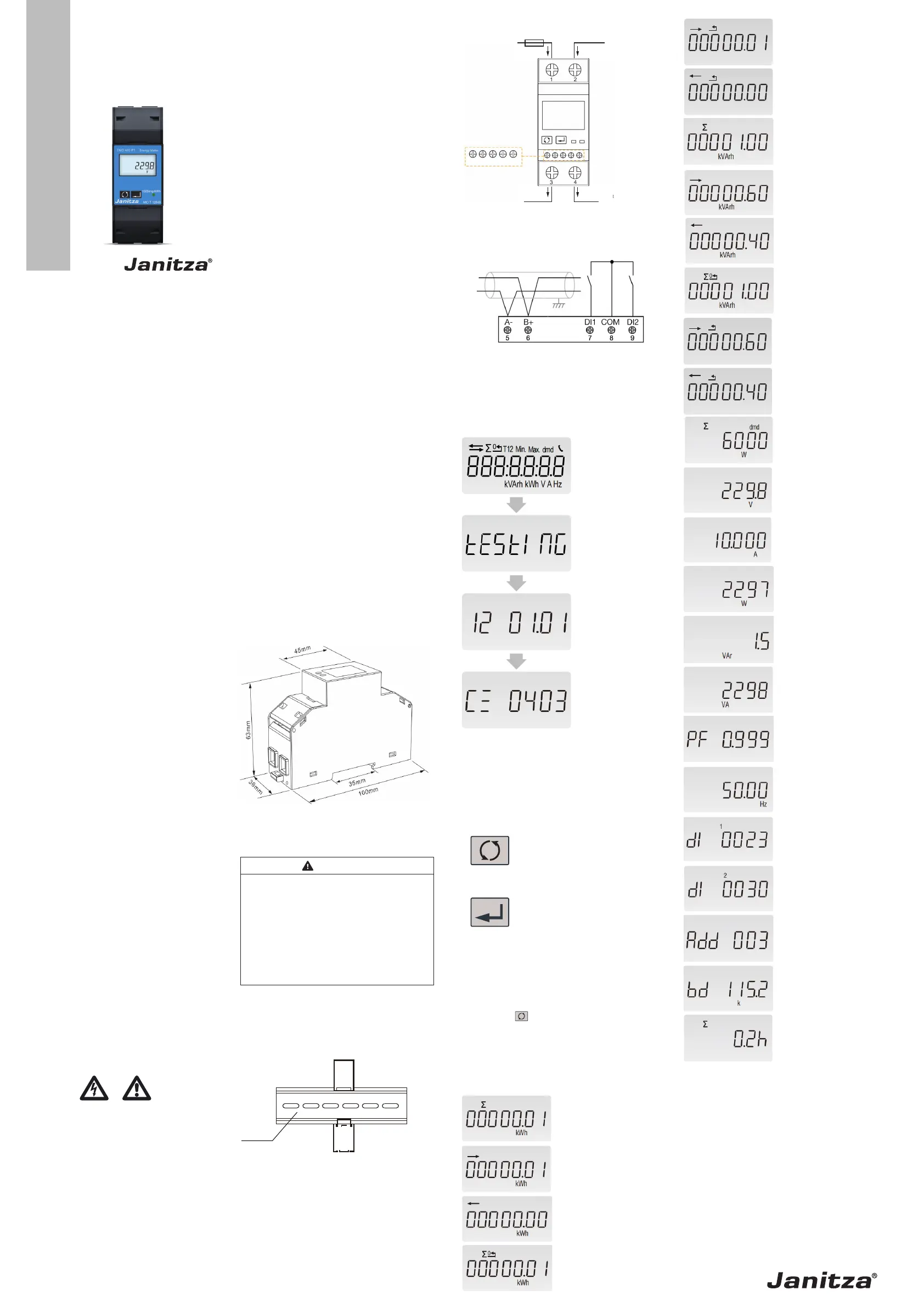
Measured value displays
To view the next measurement value, press the
Scroll button .
Note: You can activate automatic scrolling
between the measurement displays in the setup
menu. If enabled, each display is shown for an
adjustable time until it automatically switches to
the next one.
Total active energy
Example: 0.01kWh
Imported active energy
Example: 0.01kWh
Exported active energy
Example: 0.00kWh
Total resettable active
energy
Example: 0.01kWh
0
kVArh
0
kVArh
0
0
kWh
kWh
Imported active energy,
resettable
0
kVArh
0
kVArh
0
0
kWh
kWh
Exported active energy,
resettable
Total reactive energy
Example: 1.00kVArh
Imported reactive
energy
Example: 0.6kVArh
Exported reactive
energy
Example: 0.4kVArh
Total reactive energy,
resettable
Example: 1.00kVArh
0
kVArh
0
kVArh
0
0
kWh
kWh
Imported reactive
energy, resettable
0
kVArh
0
kVArh
0
0
kWh
kWh
Exported reactive
energy resettable
Total maximum power
demand
Example: 6000W
Voltage
Example: 229.8V
Current
Example: 10A
Active power
Example: 2297W
Reactive power
Example: 1.5VAr
Apparent power
Example: 2298VA
Power factor
Example: 0.999
Frequency
Example: 50.00Hz
Digital input 1 counter
value
Digital input 2 counter
value
Modbus address
Example: 003
Baud rate
Example: 115200
Continuous running
time in total
Example: 0.2h
practice requires that each critical function
is protected by at least two independent and
different means.
• The device does not have an internal fuse.
Upstream fuses for line protection are required
in all phases. If the circuit is faulty or abnormal,
the fuse will blow quickly for line protection
and safety.
• Install and operate the device according to the
Technical Data specified in this manual.
• If this device is manipulated or used in a
manner not specified by the manufacturer,
the protection provided by the device may be
impaired.
Characteristics
The device can measure and display:
• Grid voltage and frequency
• Current
• Power, maximum power demand, and power
factor
• Active energy (imported and exported)
• Reactive energy (imported and exported)
The password-protected setup menu allows to:
• Configure the device, e.g., Modbus
parameters, display settings, demand interval
time
• Reset the maximum power demand and
resettable energy values
• Change the password
Features
• Certified according to the Measuring
Instruments Directive (MID) 2014/32/EU
• Up to 100 A alternating current measurement
• Bi-directional energy measurement IMP &
EXP
• RS485 Modbus RTU for remote monitoring
and setup
• Back-lighted LCD display enables good
readability
• Two digital inputs as counters
• Din rail mounting 35mm (DINEN60715)
• Accuracy class 0.5 / C active energy
Dimensions
Figure 1. Dimensions
Installation
WARNING
Risk of injury from electrical voltage!
Touching live wires or exposed conductors
and touching dangerous device inputs can
cause severe physical harm or death.
·Switch off your installation before
starting any work! Secure the equip-
ment against being switched on!
·Verify that it is disconnected from
power! Ground and short-circuit!
·Cover or block any nearby live parts!
Observe all safety precautions before
installation!
• Mount the device on a 35mm mounting rail
in a switchboard cabinet or small distribution
board.
DIN Rail
Figure 2. Energy meter mounted on Din rail
• Connect the line inputs to terminals 1-4 as
shown in fig.3. The terminals have 25mm²
connecting capacity.
Doc. no. 2.100.144.1.d 10/2025Part. no. 3303911
MID Energy Meter
EMD485-P1
User manual
www.janitza.com
Janitza electronics GmbH
Vor dem Polstück 6
D-35633 Lahnau | Germany
Support +49 6441 9642-22
[email protected] | www.janitza.com
The device front may deviate!
Product specificaties
| Merk: | Janitza |
| Categorie: | Niet gecategoriseerd |
| Model: | EMD 485-P1 |
Heb je hulp nodig?
Als je hulp nodig hebt met Janitza EMD 485-P1 stel dan hieronder een vraag en andere gebruikers zullen je antwoorden
Handleiding Niet gecategoriseerd Janitza

2 Juni 2026
11 Februari 2026
3 Februari 2026
3 Februari 2026
2 Februari 2026
30 Januari 2026
27 Januari 2026
21 Januari 2026
13 Mei 2025
13 Mei 2025
Handleiding Niet gecategoriseerd
Nieuwste handleidingen voor Niet gecategoriseerd
23 Juli 2026
23 Juli 2026
23 Juli 2026
22 Juli 2026
22 Juli 2026
22 Juli 2026
22 Juli 2026
22 Juli 2026
22 Juli 2026
21 Juli 2026