Janitza EMD 485-P3 Handleiding
Janitza Niet gecategoriseerd EMD 485-P3
Bekijk gratis de handleiding van Janitza EMD 485-P3 (2 pagina’s), behorend tot de categorie Niet gecategoriseerd. Deze gids werd als nuttig beoordeeld door 17 mensen en kreeg gemiddeld 4.8 sterren uit 2 reviews. Heb je een vraag over Janitza EMD 485-P3 of wil je andere gebruikers van dit product iets vragen? Stel een vraag
Pagina 1/2
Introduction
This document provides instructions for installation,
operation, and maintenance.
Device description
The energy meter (device) measures and displays
important electrical parameters in three-phase four-wire
(3p4w), three-phase three-wire (3p3w), single-phase
two-wire (1p2w), and single-phase three-wire (1p3w) grid
systems. The energy measurement is bidirectional, i.e.
imported and exported energy are measured separately, so
that, for example, the solar gain of a PV system can also
be recorded.
The maximum demand of current and power can be
measured over preset periods of up to 60minutes.
The device has measurement inputs for voltages and
currents. It supports direct measurement up to 100A.
The direct connection results in a cost-saving solution,
eliminating the need for wiring the current transformers.
The device provides an RS485 serial port with Modbus
RTU protocol for communication and to enable remote
monitoring and control of the device.
Intended use
The MID-certified device is intended for the following uses:
• Measurement of power and cumulative energy in
accordance with classB EN50470-3/ ANSIC12-20:2010
in the specified grid systems.
• Installation in wheather-protected switchboard cabinets
and small distribution boards in industrial and residential
environments. The installation position is arbitrary.
• For indoor use only.
• Use in accordance with national specifications.
Improper use:
The following is considered improper use:
• Operation outside the specifications, e.g., regarding
operating/measuring voltage or current, environmental
specifications, etc.
• Too high or wrong external back-up fuse (fig.5).
• Installation in vehicles! Use of the device in non-
stationary equipment constitutes an exceptional
environmental condition and is only permissible by
special agreement.
• Installation in environments with harmful oils, acids,
gases, vapors, dusts, radiation, etc.
Safety precautions
• During normal operation, life-threatening voltages may
be present at some terminals of this device. Installation,
operation, and maintenance must only be carried out by
qualified and trained personnel in compliance with local
regulations.
Ensure that all power supplies are de-energized before
connecting the device or performing any other work.
• After installation, the terminals must not be accessible
to the user. The external installation precautions must be
sufficient to prevent hazards under fault conditions.
• This device is not intended to function as part of a
system that serves as the sole means of protection
against faults – good engineering practice requires
that each critical function is protected by at least two
independent and different means.
• The device does not have an internal fuse. Upstream
fuses for line protection are required in all phases. If the
circuit is faulty or abnormal, the fuse will blow quickly for
line protection and safety.
• Install and operate the device according to the Technical
Data specified in this manual.
• If this device is manipulated or used in a manner not
specified by the manufacturer, the protection provided by
the device may be impaired.
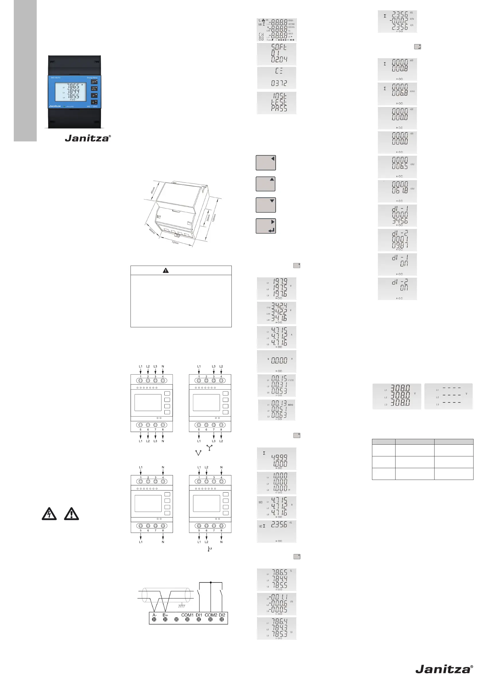
Start-up displays
ImpExp
MaxMin
m3
C
The first display lights up
all display segments and
can be used as a display
check.
The second display
indicates the firmware
installed in the device
and its build number (for
reference only).
The next display indicates
an additional internal
version number.
The device performs a self-
test and indicates the result
if the test passes.
*After a short delay, the display shows the measurement
display for active energy.
Button functions
The buttons operate as follows:
ESC
V/A
Selects the Voltage and Current
displays.
In the setup menu, this is the “Left” or
“Back” button.
MD
PF Hz
Selects the Frequency and Power
factor displays.
In the setup menu, this is the “Up”
button.
P
Selects the Power displays.
In the setup menu, this is the “Down”
button.
E
Selects the Energy displays.
In the setup menu, this is the “Enter” or
“Right” button.
Measured value displays
Voltage and current
Each time you press the
ESC
V/A
button, the next display is
shown:
Phase to neutral voltages
Phase to phase voltages
Current on each phase
Neutral current
Phase to neutral voltage
THD% (total harmonic
distortion)
(3p4w)
Current THD% for each
phase (3p4w)
Frequency, power factor, max. demand
Each time you press the
MD
PF Hz
button, the next display is
shown:
Frequency and power
factor (total)
Power factor of each phase
Maximum current demand
of each phase
Maximum power demand
Power
Each time you press the
P
button, the next display is
shown:
Instantaneous active power
in kW
Instantaneous reactive
power in kVAr
Instantaneous apparent
power in kVA
Total kW, kVArh, kVA
Energy
Each time you press the
E
button, the next display is
shown:
Total active energy in kWh
Total reactive energy in
kVArh
Imp
Imp: Imported active
energy in kWh
Exp
Exp: Exported active
energy in kWh
Imp
Imp: Imported reactive
energy in kVArh
Exp
Exp: Exported reactive
energy in kVArh
Digital input 1 counter
value
Digital input 2 counter
value
Digital input 1 state (on/off)
Digital input 2 state (on/off)
Underrange and overrange
Indication on the display
On the voltage, current, and power displays, etc., when the
measured values are below the measurement range, the
display shows “0”.
When the measured values are above the measurement
range, two displays alternate. One shows the actual
measured value and the other shows “-“ symbols.
Example: If the voltage is exceeded, the display alternates
at short intervals between the following two displays:
Display 1
(measured value)
Display 2
(overrange indication)
Defined thresholds
UnderrangeOverrange
Voltage< 100V
(for L-N / L-L)
> 480V
(for L-N / L-L)
Current< 0.04A
(for L-N / L-L)
> 100A
(for L-N / L-L)
Power< 8W (VAr)(VA)
(for L-N / L-L)
> 48000W(VAr)(VA)
(for L-N / L-L)
Note: The threshold values of underrange and overrange
are the secondary values of the meter.
Characteristics
The device can measure and display:
• Grid voltage and THD% (total harmonic distortion) of all
phases
• Grid frequency
• Current, current demand and current THD% of all phases
• Power, maximum power demand, and power factor
• Active and reactive energy (imported and exported)
The password-protected setup menu allows to:
• Select the grid system: 3p4w, 3p3w, 1p2w, 1p3w
• Configure the device, e.g., Modbus parameters, display
settings, demand interval time
• Reset the max. demand and the digital input counters
• Change the password
Features
• Certified according to the Measuring Instruments
Directive (MID) 2014/32/EU.
• Up to 100 A alternating current measurement
• Bidirectional energy measurement IMP & EXP
• Two digital inputs as counters
• RS485 Modbus RTU for remote monitoring and setup
• Din rail mounting 35mm (DINEN60715)
• Accuracy class C active energy
Dimensions
Installation
WARNING
Risk of injury from electrical voltage!
Touching live wires or exposed conductors and
touching dangerous device inputs can cause
severe physical harm or death.
·Switch off your installation before starting
any work! Secure the equipment against
being switched on!
·Verify that it is disconnected from power!
Ground and short-circuit!
·Cover or block any nearby live parts!
Observe all safety precautions before installation!
• Mount the device on a 35mm mounting rail in a
switchboard cabinet or small distribution board.
• Connect the line inputs to the terminals as shown. The
terminals 1-8 have 25mm² connecting capacity.
A-B+COM1COM2DI2DI1
A-B+COM1COM2DI2DI1
A-B+COM1COM2DI2DI1
A-B+COM1COM2DI2DI1
1p3w gibt es nicht als Einstellung auf 485-P3
Figure 1. Left: Three-phase four-wire (3p4w)
1p2w3p4w3p3w
Right: Three-phase three-wire (3p3w)
1p2w3p4w3p3w
A-B+COM1COM2DI2DI1
A-B+COM1COM2DI2DI1
A-B+COM1COM2DI2DI1
A-B+COM1COM2DI2DI1
1p3w gibt es nicht als Einstellung auf 485-P3
Figure 2. Left: Single-phase two-wire (1p2w)
1p2w3p4w3p3w
Right:Single-phase (split-phase) three-wire (1p3w).
Note:The 1p3w grid system is not covered by the MID
directive.
• Connect RS485 and/or digital inputs if required.
P3
A
B
Figure 3. Connection of RS485 and digital inputs
Doc. no. 2.100.143.1.c 10/2025Part. no. 3303910
MID Energy Meter
EMD485-P3
User manual
www.janitza.com
Janitza electronics GmbH
Vor dem Polstück 6
D-35633 Lahnau | Germany
Support +49 6441 9642-22
[email protected] | www.janitza.com
The device front may deviate!
Product specificaties
| Merk: | Janitza |
| Categorie: | Niet gecategoriseerd |
| Model: | EMD 485-P3 |
Heb je hulp nodig?
Als je hulp nodig hebt met Janitza EMD 485-P3 stel dan hieronder een vraag en andere gebruikers zullen je antwoorden
Handleiding Niet gecategoriseerd Janitza

2 Juni 2026
11 Februari 2026
3 Februari 2026
3 Februari 2026
2 Februari 2026
30 Januari 2026
27 Januari 2026
21 Januari 2026
13 Mei 2025
13 Mei 2025
Handleiding Niet gecategoriseerd
Nieuwste handleidingen voor Niet gecategoriseerd
23 Juli 2026
23 Juli 2026
23 Juli 2026
22 Juli 2026
22 Juli 2026
22 Juli 2026
22 Juli 2026
22 Juli 2026
22 Juli 2026
21 Juli 2026